
Supra L6-2997cc 3.0L DOHC MFI (1998)
Hydraulic Control Assembly - Antilock Brakes: Testing and Inspection
ON-VEHICLE INSPECTION
1. Inspect battery positive voltage.
Battery positive voltage: 10 - 14 Volts
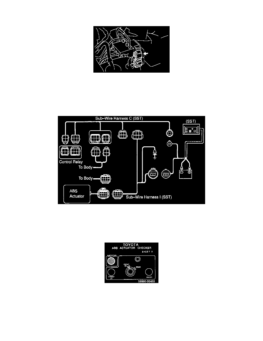
2. Disconnect connector from actuator.
3. Disconnect 2 connectors from control relay.
4. Connect actuator checker Special Service Tool (SST) 09990-00150, 09990-00200, 09990-00300 or equivalent, to actuator.
a. Connect the actuator checker (SST) to the actuator side wire harnesses via the sub-wire harnesses (SST), as shown.
b. Connect the red cable of the checker to the battery positive (+) terminal and black cable to the negative (-) terminal. Connect the black cable of
the sub-wire harnesses to the battery negative (-) terminal or body ground.
c. Place "SHEET O" SST 09990-00420 on the actuator checker.
5. Inspect brake actuator operation of front Left-Hand (LH) wheel.
a. Start the engine, and run it at idle.
b. Turn the selector switch of the actuator checker to "FRONT RH" position.
c. Push and hold in the MOTOR switch for a few seconds. Make sure that you can hear the motor run.
d. Depress the brake pedal and hold it for about 15 seconds, and check that the pedal does not go down.