
T100 Regular Cab Pickup 2WD L4-2693cc 2.7L DOHC MFI (1998)
1-2:
Closed with brake pedal depressed
E 4 (A), E 5 (B), E 6 (C), E 7 (D) ENGINE CONTROL MODULE
S1-E1:
9-14 Volts with ignition SW ON position
S2, SL-E1:
0-1.5 Volts with ignition SW ON position
BK-E1:
7.5-14 Volts with brake pedal depressed
0-1.5 Volts with brake pedal released
THW-E2:
0.2-1.0 Volts with coolant temp. 80° C (176° F)
VTA-E2:
0.3-0.8 Volts with throttle valve fully closed
3.2-4.9 Volts with throttle valve fully open
VCC-E2:
4.5-5.5 Volts with ignition SW ON position
OD2-E1:
9-14 Volts O/D main SW turned ON
0 Volts O/D main SW turned OFF
SP1-E1:
Pulse generation cruise control main SW OFF and vehicle moving
SP2+-E1:
Pulse generation with vehicle moving
2-E1:
10-14 Volts with shift lever at 2 position
0-2 Volts with shift lever at expect 2 position
L-E1:
10-14 Volts with shift lever at L position
0-2 Volts with shift lever at expect L position
+B-E1:
9-14 Volts with ignition SW ON position
BATT-E1:
Always 9-14 Volts
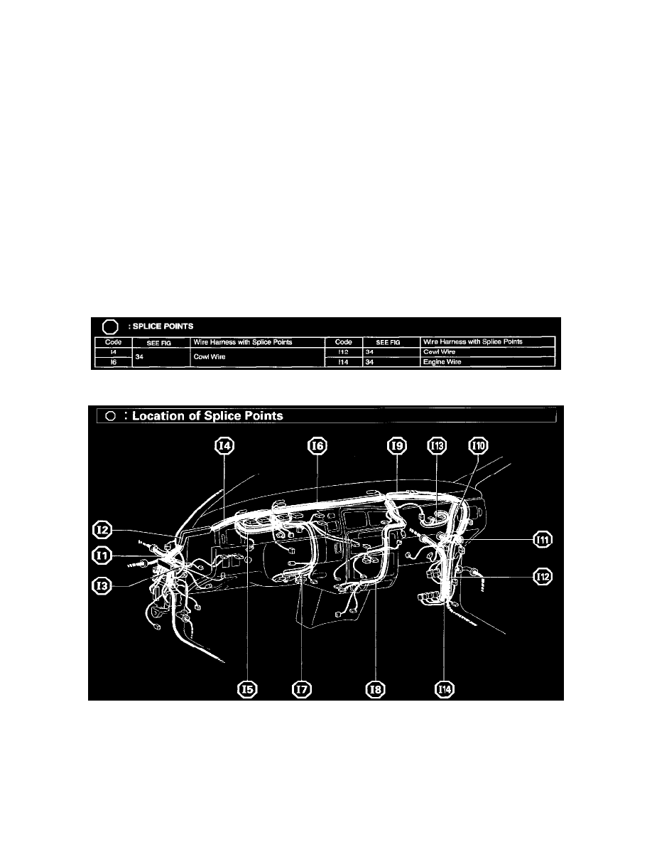
Splice Points
Splice Points
Location Of Splice Points (Fig 34)
System Outline
Previous automatic transmissions have selected each gear shift using mechanically controlled throttle hydraulic pressure, governor hydraulic pressure
and lock-up hydraulic pressure. The electronically controlled transmission, however, electrically controls the governor pressure and lock-up pressure
through the solenoid valve. Engine control module control of the solenoid valve based on the input signals from each sensor makes smooth driving
possible by shift selection for each gear which is most appropriate to the driving conditions at that time.