
Tacoma Extra Cab 2WD L4-2438cc 2.4L DOHC MFI (1997)
D15 DOOR COURTESY SW LH
1-Ground:
Closed with Door open
I15-A SEAT BELT WARNING RELAY (INTEGRATION RELAY)
7-Ground:
Always Continuity
6-Ground:
Approx. 12 Volts with Ignition SW ON
12-Ground:
Always approx. 12 Volts
A-5-Ground: Continuous with Door open
A-10-Ground: Approx. 12 Volts with Ignition Key in Cylinder
A-2-Ground: 0 Volts for 4-8 Seconds with Ignition SW ON and 12 Volts 4-8 Seconds after Ignition SW ON
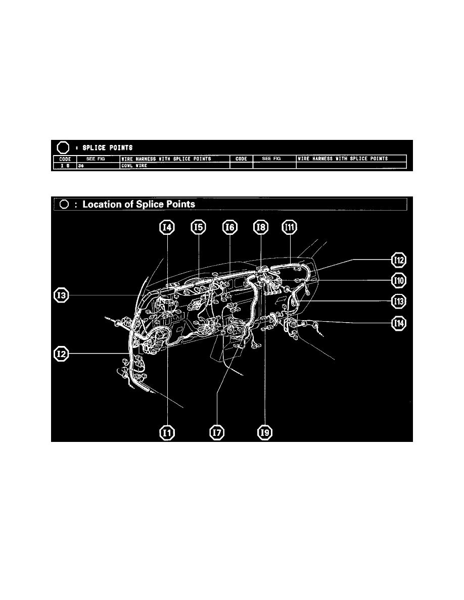
Splice Points
Splice Points
Location Of Splice Points (Fig 36)
System Outline
Current always flows to TERMINAL 12 of the integration relay through the DOME fuse.
1. SEAT BELT WARNING SYSTEM
When the Ignition SW is turned ON, current flows from the GAUGE fuse to TERMINAL 6 of the integration relay. At the same time, current
flows to TERMINAL A-2 of the relay from the GAUGE fuse through the Seat Belt Warning Light [Comb. Meter]. This current activates the
integration relay and, for Approx. 4-8 Seconds, current flowing through the warning light flows from TERMINAL A-2 of relay --> TERMINAL
7 --> GROUND, causing the warning Light to Light up. At the same time as the warning Light Lights up, a buckle SW ON signal is input to
TERMINAL A-3 of relay, the current flowing from TERMINAL 12 of the relay flows to TERMINAL 7 --> GROUND and the Seat Belt
Warning Buzzer Sounds for Approx. 4-8 Seconds. However, if the Seat Belt is put ON (Buckle SW OFF) during this period (While The Buzzer
Is Sounding), signal input to TERMINAL A-3 of relay Stops and the current flow from TERMINAL 12 of the relay --> TERMINAL 7 -->
GROUND is cut, causing the buzzer to stop.