|
Valve Bridges, Remove and Install
 Remove Remove
Remove air cleaner housing with hot film mass air flow meter and
air intake hose - see illustration "Air duct X 20 DTL, Y 20 DTL"
and "Air duct Y 20 DTH up to MY 2003" and "Air duct Y 20 DTH as of
MY 2003, Y 22 DTR".
Remove cylinder head cover – see operation "Cylinder Head
Cover, Remove and Install".
Remove vacuum pump from cylinder head and lay aside to rear
– see operation "Vacuum Pump, Remove and Install".
Remove ribbed V-belt tensioner – see operation "Ribbed
V-belt Tensioner Assembly, Remove and Install".
Lock engine at 1st cylinder TDC – see operation "Engine,
Lock at 1st Cylinder TDC (Timing, Check)".
Remove camshaft – see operation "Camshaft, Remove and
Install".
Caution
|
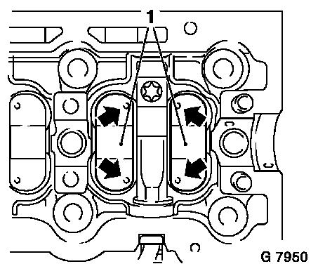
When removing traverse injection nozzles, place to one side in
correct order to ensure correct allocation when re-installing. Mark
(arrows) on valve bridges are located on side of injection nozzle
traverse.
Remove
Remove valve bridge (1) from cylinder head – note
installation position.
 Install
Insert valve bridges (1) into cylinder head – note
installation position – marks (arrows) on valve bridges are
located on side of traverse injection nozzle.
|
|
Install camshaft – see operation "Camshaft, Remove and
Install".
Install ribbed V-belt tensioner – see operation "Ribbed
V-belt Tensioner Assembly, Remove and Install".
Install vacuum pump – see operation "Vacuum Pump, Remove
and Install".
Install cylinder head cover – see operation "Cylinder Head
Cover, Remove and Install".
Install air cleaner housing with hot film mass air flow meter
and air intake hose - see illustration "Air duct X 20 DTL, Y 20
DTL" and "Air duct Y 20 DTH up to MY 2003" and "Air duct Y 20 DTH
as of MY 2003, Y 22 DTR".
|
