vauxhall Workshop Repair Guides

Vauxhall Workshop Service and Repair Manuals

Oil Pump, Remove and Install > < Seal Ring - Timing Case, Replace / Front Seal Ring - Crankshaft, Replace

Timing Case, Remove and Install

Note:   The timing case must be removed for the following operations.

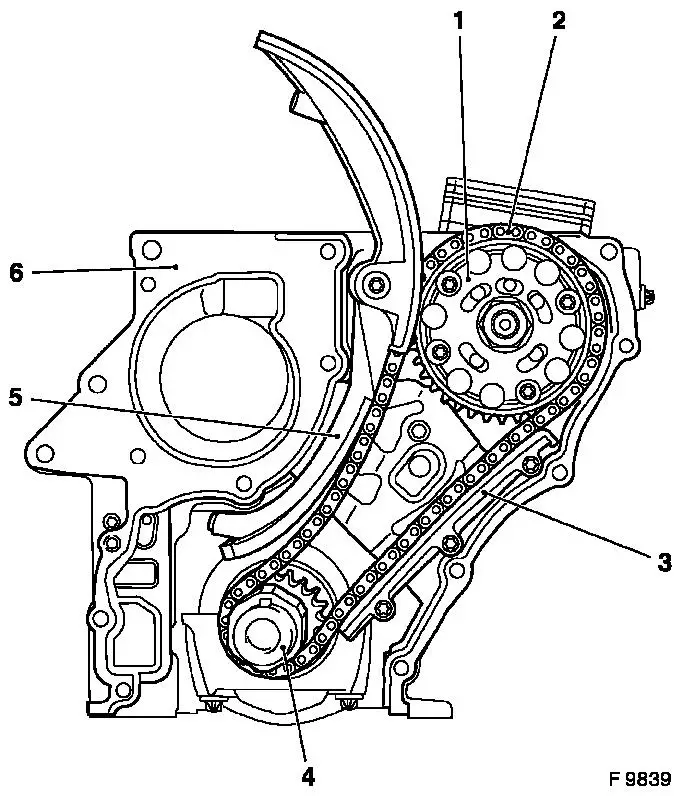
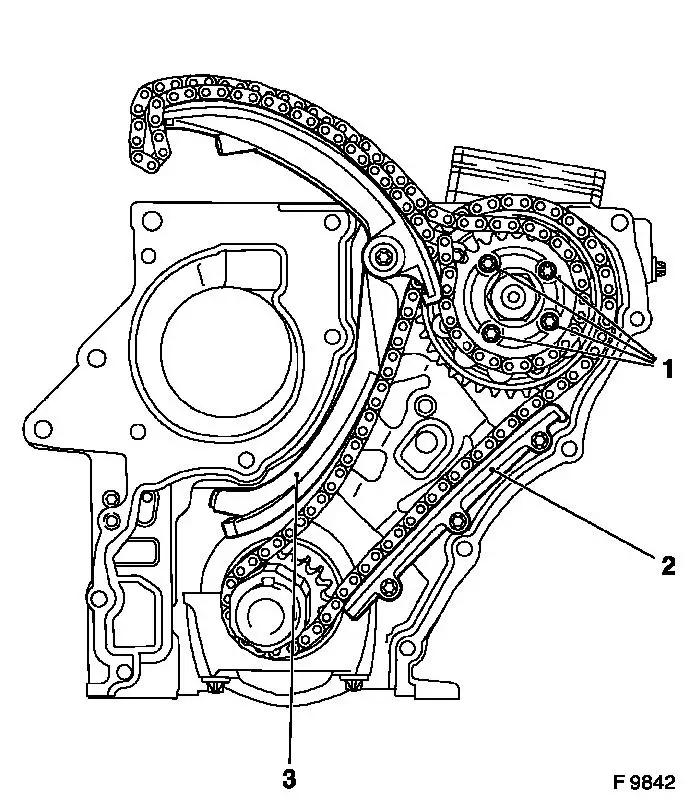
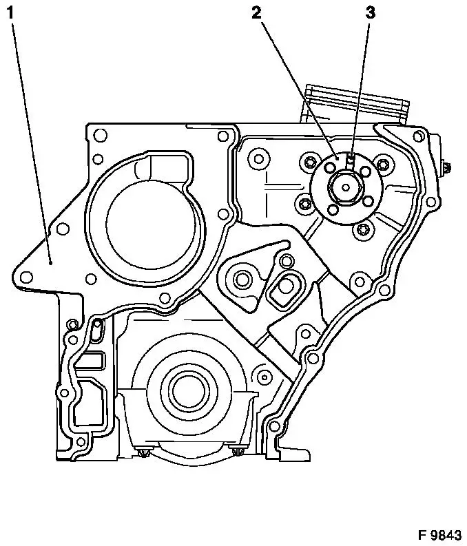
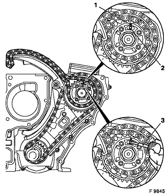
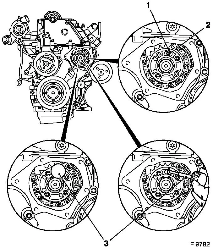
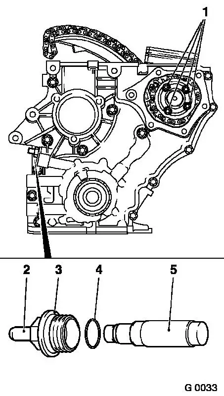
1. Duplex Injection Pump Sprocket, Remove and Install

2. Duplex Timing Chain, Remove and Install

3. Guide Rail for Duplex Timing Chain, Remove and Install

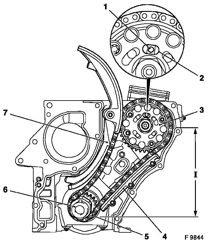
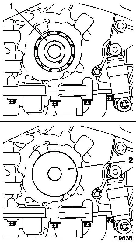
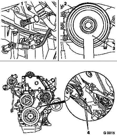
4. Crankshaft Sprocket, Remove and Install

5. Timing Chain Tension Rails, Remove and Install

6. Gasket, Timing Case, Replace

7. Oil Pump, Remove and Install (not shown in illustration F 9839)

Object Number: 2396037  Size: DEFAULT

  Remove

1.   Remove oil pan
2.   Remove air cleaner housing with hot film mass air flow meter and air intake hose
•   X 20 DTL and Y 20 DTH
•   Y 20 DTH up to MY 2003
•   Y 20 DTH as of MY 2003 and Y 22 DTR LUREF_1.gif
3.   Remove cylinder head cover
4.   Remove vacuum pump from cylinder head and place to the rear LUREF_1.gif
5.   Remove ribbed V-belt
6.   Remove ribbed V-belt tensioner LUREF_1.gif
7.   Lock engine on no. 1 cylinder "Ignition TDC" LUREF_1.gif
8.   Remove cylinder head
9.   Detach cable connections (1) and (2) from alternator
10.   Remove lower alternator fastening bolt and remove alternator
11.   Remove ribbed V-belt guide roller
12.   Remove crankshaft locking pin KM-929 (3)
Object Number: 2398962  Size: DEFAULT


13.   Loosen ribbed V-belt pulley crankshaft
Note:   Second installer required
•   Loosen bolt (1)
Note:   Do not unscrew
Up to MY 2003 and engine number 17K44148: Counterhold using KM-977-1 (2) together with KM-956-1
From MY 2003 and engine number 17K44149: Counterhold using KM-6619 (2) together with KM-956-1
14.   Reinsert crankshaft locking pin KM-929 (3) to stop in aperture for crankshaft pulse pick-up
•   In this position, the marks (4) must align
15.   Remove crankshaft ribbed V-belt pulley
•   Unscrew bolt
Object Number: 2396167  Size: DEFAULT


16.   Remove Duplex chain tensioner (1)
17.   Detach timing case (2) from cylinder block
Note:   Note different bolt lengths
18.   Lever seal ring (3) out of timing case with suitable tool
Note:   Take care not to damage sealing surfaces
Object Number: 2396039  Size: DEFAULT


19.   Remove fastening bolts (1), and remove simplex injection pump gear with simplex timing chain
Note:   For Y 20 DTH from MY 2003 and Y 22 DTR 5 fastening bolts
20.   Remove guide rail for duplex timing chain (2) from cylinder block
21.   Remove timing chain tension rails (3) from cylinder block
Object Number: 2396040  Size: DEFAULT


22.   Remove crankshaft sprocket with duplex timing chain and duplex fuel injection pump sprocket
23.   Remove timing case gasket

  Install

24.   Clean sealing surfaces and remove gasket remnants.
25.   Check all parts and replace if necessary
26.   Insert new gasket (1) in cylinder block
27.   Recess in fuel injection pump flange (2) must align with retaining bore (3) in fuel injection pump
Object Number: 2396041  Size: DEFAULT


Important:   Ensure that recess is positioned in fuel injection pump flange and that retaining bore (1) is centrally positioned in oblong hole (2) on duplex fuel injection pump gear – tension side (I) must be taut
28.   Place crankshaft sprocket (6) with duplex timing chain (5) and duplex fuel injection pump sprocket (3) on crankshaft or fuel injection pump flange
29.   Attach guide rail of duplex timing chain (4) to cylinder block – tightening torque 8 Nm / 6 lbf. ft
30.   Attach tension rail timing chains (7) to cylinder block – tightening torque 20 Nm / 15 lbf. ft.
Object Number: 2396042  Size: DEFAULT


31.   Put Simplex injection pump wheel onto injection pump flange and hand-tighten new fastening bolts
32.   Place simplex timing chain on simplex injection pump gear and suspend over timing chain tension rail (simplex)
•   Arrow (1) on simplex fuel injection pump sprocket must align with recess in fuel injection pump flange and retaining bore (2) in fuel injection pump
Note:   Injection pump locking pin KM-927 (3) must be able to be removed and installed under suction
Object Number: 2396043  Size: DEFAULT


33.   Attach timing case to cylinder block – tighten fastening bolts uniformly – tightening torque 20 Nm / 15 lbf. ft.
34.   Place seal ring on protective sleeve KM-935-1 (1) and position in timing case without tilting
35.   Apply seal ring to protective sleeve using KM-935-2 (2), and press in seal ring until it lies flush in the timing case
•   Use the fastening bolt of the torsional vibration damper
Object Number: 2396036  Size: DEFAULT


36.   Remove crankshaft locking pin KM-929 (1) and, if installed, injection pump locking pin KM-927
37.   Fasten ribbed V-belt pulley crankshaft (2)
•   Tighten new bolt 150 Nm +45° + 15°
Note:   Second installer required
Up to MY 2003 and engine number 17K44148: Counterhold using KM-977-1 (3) together with KM-956-1
From MY 2003 and engine number 17K44149: Counterhold using KM-6619 (3) together with KM-956-1
38.   Reinsert crankshaft locking pin KM-929 (1) to stop in aperture for crankshaft pulse pick-up
39.   In this position, the marks (4) must align
Object Number: 2396168  Size: DEFAULT


40.   Arrow (1) on simplex fuel injection pump sprocket must align with recess in fuel injection pump flange and retaining bore (2) in fuel injection pump
41.   Insert injection pump locking pin KM-927 (3) in retaining bore of injection pump
Object Number: 2395988  Size: DEFAULT


Important:   A distinction must be made between versions with and without release bolts (2). In versions with release bolts the chain tensioner must be untightened using the release bolt after installation
42.   Insert duplex chain tensioner (5) in timing case
Note:   closed side of chain tensioner must point to tensioner blade
•   Install duplex chain tensioner closure bolt (3) with new seal ring (4) - tightening torque 60 Nm
43.   It must be possible to push in release bolt up to stop with thumb and for it to slide back to its original position automatically – the release bolt can no longer be pushed in once the oil pressure has built up
44.   Remove injection pump locking pin KM-927 .
45.   Tightening fastening bolts (1) with bolt strength of 10.9 for simplex injection pump gear - tightening torque 28 Nm
Note:   For Y 20 DTH from MY 2003 and Y 22 DTR 5 fastening bolts.
46.   Recheck that injection pump locking pin KM-927 can be installed and removed under suction
Object Number: 2396176  Size: DEFAULT


47.   Attach ribbed V-belt guide roller to support – tightening torque 35 Nm / 26 lbf. ft.
48.   Attach alternator with lower fastening bolt to timing case and cylinder block - tightening torque 35 Nm / 26 lbf. ft.
Note:   Tighten to torque only after installing the upper fastening bolt
49.   Attach cable connections to alternator
50.   Install cylinder head
51.   Attach vacuum pump to cylinder head LUREF_1.gif
52.   Install cylinder head cover
53.   Install ribbed V-belt tensioner LUREF_1.gif
54.   Insert ribbed V-belt
55.   Install air cleaner housing with hot film mass air flow meter and air intake hose
•   X 20 DTL and Y 20 DTH
•   Y 20 DTH up to MY 2003
•   Y 20 DTH as of MY 2003 and Y 22 DTR LUREF_1.gif
56.   Install oil pan

Related Literature Units
-
-

Oil Pump, Remove and Install > < Seal Ring - Timing Case, Replace / Front Seal Ring - Crankshaft, Replace