|
Replace all valve stem seals (cylinder head
installed)
 Remove Remove
| 1. |
Remove hydraulic valve lifter
| • |
See operation "Camshafts, Remove and Install"
|
|
| 2. |
Remove spark plugs
| • |
See operation "Spark Plugs, Remove and Install"
|
|
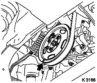
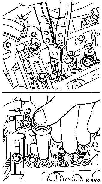
| 3. |
Make alignment mark
| • |
On crankshaft belt pulley (arrow)
Note: 180° offset
in respect of the marking, ignition TDC cylinder no. 1
|
|
|
|
| 4. |
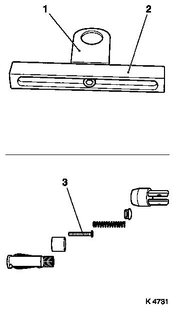
Prepare automated valve spring lever MKM-6086
| • |
Adjust supports MKM-6086-6 (2)
| – |
Adjust support heads (1) centrally in respect of the support
feet (2) and tighten
|
|
| • |
Complete lever arm MKM-6086-7
| – |
With joint MKM-6086-8 and removal
head MKM-6086-10
|
|
|
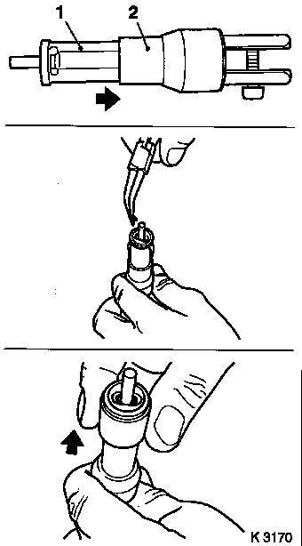
| 5. |
Complete assembly kit MKM-6086-200
| • |
Insert thrust piece MKM-6086-200-10
(3)
Note: Note
manufacturer's provisions
|
|
|
|
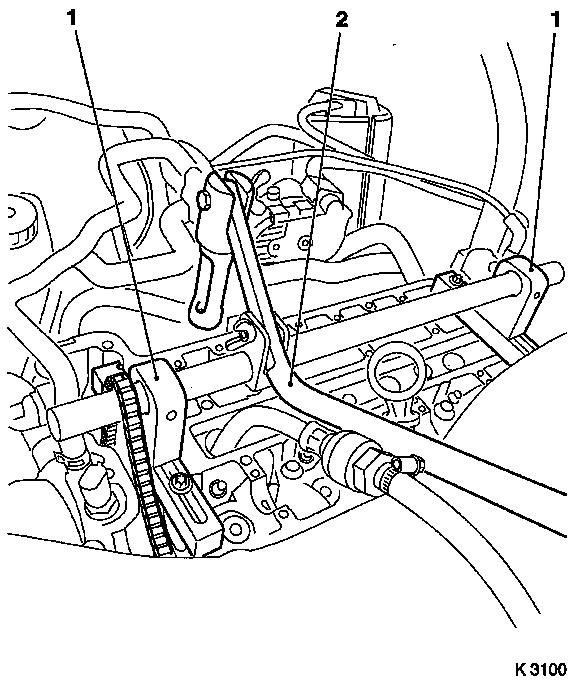
| 6. |
Attach automatic valve spring lever MKM-6086
| • |
Attach supports MKM-6086-6 (1)
| – |
Push assembly shaft into supports
Note: Align assembly
shaft so that it is centred over spark plug bore
|
|
| • |
Install lever arm MKM-6086-7 (2)
Note: Removal head must
point towards intake side
|
| • |
Secure installation shaft
|
|
| 7. |
Install compressed air adapter
| • |
Screw into spark plug thread, cylinder no. 1
|
| • |
Apply compressed air to cylinder no. 1
|
|
|
|
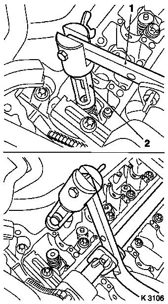
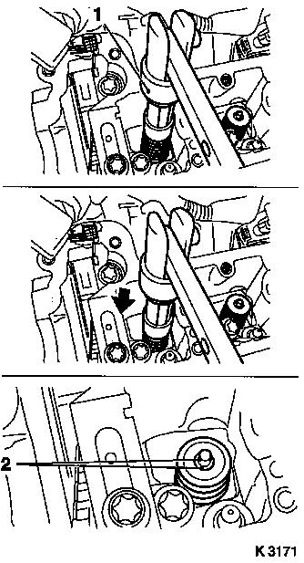
| 8. |
Remove intake valve springs on cylinder no. 1
| • |
Carefully push valve springs downwards
| – |
With lever arm (1)
Note: Removal head (2)
must stand vertically above valve stem
|
|
Important: Observe correct
assignment
|
| • |
Remove valve cotters, valve heads, valve springs
Note: Do not use
magnetic tools
|
|
|
|
| 9. |
Replace valve stem seals
| • |
Place new valve stem seal on valve stem
|
| • |
Drive in as far as the stop with KM-958
|
|
|
|
| 10. |
Install intake valve springs on cylinder no. 1
| • |
Insert valve springs and valve heads
|
| • |
Insert valve cotters into assembly head (1)
| – |
Slide plastic clamping sleeve (2) in direction of lever arm
mount
|
Important: Insert valve cotters
with tapered end towards valve
|
| – |
Insert valve cotters
|
| – |
Slide plastic clamping sleeve in direction of valve (arrow)
|
|
|
|
|
| 11. |
Install valve cotters
| • |
Attach assembly head (1) to lever arm
|
Important: Assembly head must
stand vertically above valve stem. Valve cotters (2) must engage
audibly
|
| • |
Carefully push valve springs downwards with lever arm
(arrow)
|
Important: Do not make a 2nd
attempt without checking that both valve cotters are seated in the
assembly head. Check seat of valve cotters. Ensure that compressed
air is being applied.
|
| • |
|
|
|
|
| 12. |
Transfer lever arm
| • |
Install lever arm
Note: Removal head must
point towards exhaust side
|
|
| 13. |
Remove exhaust valve springs on cylinder no. 1
| • |
Carefully push valve springs downwards with lever arm
Note: Removal head must
stand vertical above valve stem
|
Important: Observe correct
assignment
|
| • |
Remove valve cotters, valve heads, valve springs
Note: Do not use
magnetic tools
|
|
| 14. |
Replace valve stem seals
| • |
Place new valve stem seal on valve stem
|
| • |
Drive in as far as the stop with KM-958
|
|
| 15. |
Install exhaust valve springs on cylinder no. 1
| • |
Insert valve springs and valve heads
|
| • |
Insert valve cotters into assembly head (1)
| – |
Slide plastic clamping sleeve (2) in direction of lever arm
mount
|
Important: Insert valve cotters
with tapered end towards valve
|
| – |
Insert valve cotters
|
| – |
Slide plastic clamping sleeve in direction of valve (arrow)
|
|
|
| 16. |
Install valve cotters
| • |
Attach assembly head (1) to lever arm
|
Important: Assembly head must
stand vertically above valve stem. Valve cotters (2) must engage
audibly
|
| • |
Carefully push valve springs downwards with lever arm
(arrow)
Note: Do not make a 2nd
attempt without checking that both valve cotters are seated in the
assembly head. Check seat of valve cotters. Ensure that compressed
air is being applied.
|
|
| 17. |
Transfer compressed air adapter
| • |
Interrupt compressed air feed
|
| • |
Unscrew from spark plug thread, cylinder no. 1
|
| • |
Screw into spark plug thread, cylinder no. 4
|
| • |
Apply compressed air to cylinder no. 4
|
|
| 19. |
Replace valve stem seals, cylinder no. 4
|
| 20. |
Interrupt compressed air feed
|
| 21. |
Remove crankshaft lock KM-952
|
| 22. |
Adjust ignition TDC of cylinder no. 3
| • |
Pull timing chain upwards
|
| • |
Turn crankshaft evenly (180°)
Note: The mark on the
crankshaft belt pulley must align with the lug on the timing
case.
|
|
| 24. |
Transfer compressed air adapter
| • |
Interrupt compressed air feed
|
| • |
Unscrew from spark plug thread, cylinder no. 4
|
| • |
Screw into spark plug thread, cylinder no. 2
|
| • |
Apply compressed air to cylinder no. 2
|
|
| 25. |
Replace valve stem seals, cylinder no. 2
|
| 26. |
Transfer compressed air adapter
| • |
Interrupt compressed air feed
|
| • |
Unscrew from spark plug thread, cylinder no. 2
|
| • |
Screw into spark plug thread, cylinder no. 3
|
| • |
Apply compressed air to cylinder no. 3
|
|
| 27. |
Replace valve stem seals, cylinder no. 3
|
| 28. |
Interrupt compressed air feed
|
| 29. |
Detach automatic valve spring lever
|
| 30. |
Remove compressed air adapter
|
| 33. |
Lock crankshaft
| • |
Pull timing chain upwards
|
| • |
Turn crankshaft evenly until KM-952
engages
|
|
 Install
| 35. |
Install spark plugs
| • |
See operation "Spark Plugs, Remove and Install"
|
|
| 36. |
Visually check components
| • |
Camshafts, camshaft bearing cap, cylinder head, roller cam
follower, hydraulic valve lifter
|
|
| 37. |
Install hydraulic valve lifter, roller cam follower and
camshafts
| • |
See operation "Camshafts, Remove and Install"
|
|
|
