|
Engine, Remove and Install
Note: The operation
"Engine, Remove and Install" is described for an X 16 XEL engine
with, AC and LHD. For models equipped differently, proceed
analogously.
Cable ties detached for removal of the engine must be reattached
at the same location on installation.
Caution
For vehicles with airbag: Turn steering to straight ahead
position, remove ignition key and engage steering lock.
 Remove Remove
|
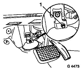
Remove clamping bolt (1) on steering column intermediate spindle
(interior).
Drain air conditioning – see operation "Air Conditioning,
Drain" in group "D".
Open coolant drain bolt – collect escaping coolant.
|
|
|
Remove engine cover.
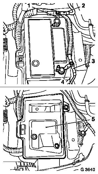
Disconnect ground cable (3) from ground connection and
disconnect ground connection (4) from battery.
Disconnect positive lead (2) from positive terminal and
disconnect positive terminal (1) from battery.
Remove battery.
Detach battery support (5) from body.
Remove air cleaner housing – see illustration "Air Ducts X
14 XE, Z 14 XE, X 16 XEL,Z 16 XE, Z 16 YNG" or "Air Ducts X 18 XE1,
Z 18 XE, Z 18 XEL".
|
|
|
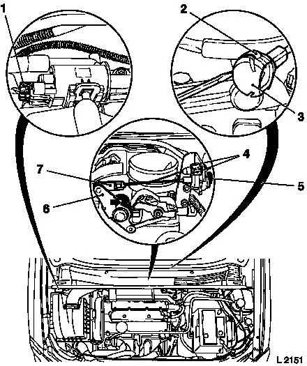
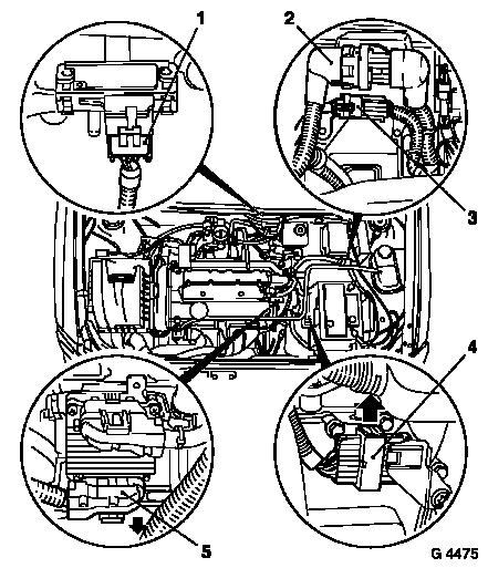
Disconnect wiring harness plug (1) from tank vent valve.
For X 18 XE1: press throttle valve lever (6) in direction of
arrow and hold in position.
Lift retainer (2) with screwdriver and remove ball socket (3)
from ball head.
If present: remove shackle for cruise control Bowden cable
(7).
Compress guide for cruise control Bowden cable at the two
retaining pins (4) and remove from bracket – lay cruise
control Bowden cable aside.
Detach retaining clamp (5) upwards and pull guide for
accelerator Bowden cable from bracket in direction of arrow and lay
aside.
|
|
|
Note: It must be
ensured that the valve support is not damaged when disconnecting
the tank vent valve hose from the valve body. Damaged valves must
be replaced.
Caution
Damaged valve supports can cause a vehicle fire as a result of
leaks.
Remove
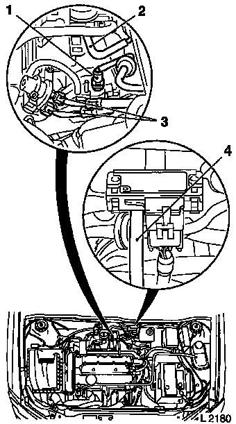
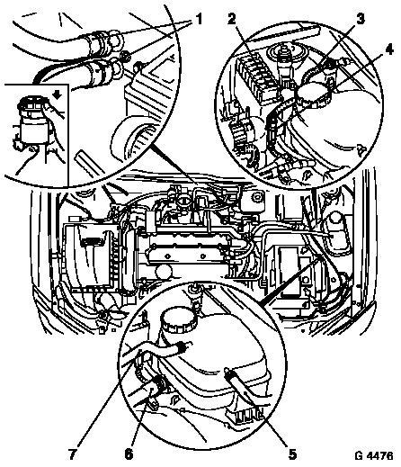
Remove tank vent valve hose (2) from tank vent valve.
Reduce fuel pressure with Pressure Tester KM-J-34730-91 via
testing port – collect escaping fuel in suitable container
– observe safety regulations and national legislation.
Remove fuel lines (3) from fuel distributor pipe.
For Z 16 YNG: Remove CNG low pressure line from CNG distributor
pipe - see operation "CNG Low Pressure Line, Remove and
Install"
Disconnect brake servo vacuum line (1) and vacuum hose for
intake manifold pressure sensor (4) from inlet manifold.
|
|
|
Wiring harness plug
- Intake manifold pressure sensor (1)
- Multiplug (twist connection) (2)
- Multiplug (green) (3)
- Engine control unit wiring harness plug (5)
- For version with automatic transmission: Transmission wiring
harness plug (4)
disconnect or detach and put cable bunch out of way.
|
|
|
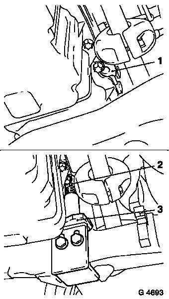
Disconnect steering cable bunch and put
out of way:
- Withdraw fuse carrier (2) from bracket
- Disconnect wiring harness plug (4)
- Detach ground cable (3) from body
Release coolant hose (1) in direction of arrow and detach from
heater core.
Detach coolant hose (7) from throttle body.
Detach coolant hose (6) from coolant pipe.
Detach coolant hose (5) from radiator.
|
|
|
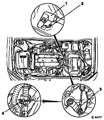
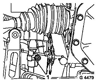
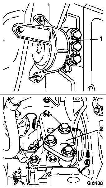
For version with manual transmission: Release pressure line with
connector (1) from pressure line for central release mechanism on
clutch housing – detach clutch pressure line for this.
Release clamp (2) with screwdriver and remove – then bend
clamp slightly together and re-insert in connector.
For version with automatic transmission: Push selector actuation
cable (3) off actuation lever. Lever out retainer (4) with
screwdriver and unclip selector actuation cable from
counterpart.
|
|
|
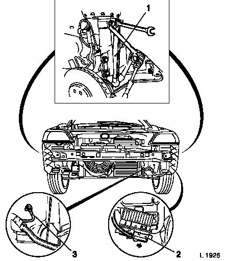
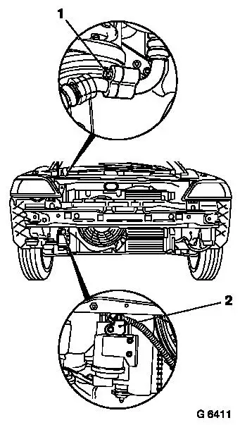
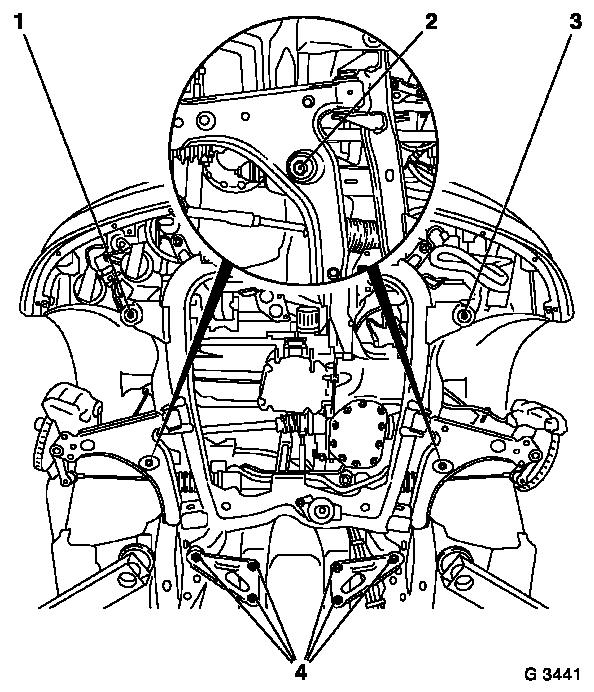
Remove front wheels.
Remove front panelling – see operation "Front Panelling,
Remove and Install " in group "A".
Detach swing arm (1) on both sides from spring strut support
tube – counterhold with op-ended spanner at the two flattened
surfaces.
Withdraw axle shafts on both sides from wheel hub (do not remove
from transmission) – see operation "Axle Shaft, Remove and
Install" in group "E".
Remove lower engine splash guard.
Unlock wiring harness plug (2) in direction of arrow and detach
from cooling module control unit.
Disconnect ground cable (3) from body.
|
|
|
Remove front exhaust pipe with catalytic converter and centre
muffler.
For version with manual transmission: Release clamp (1) from
shift rod and remove shift guide from shift rod.
|
|
|
Note: The drive unit
must be aligned to the front axle body using KM-6173 and KM-6001-A
in order to ensure correct alignment of the drive unit after
releasing the fastening bolts for the right and left engine damping
blocks. The attachment of KM-6173 and KM-6001-A is described in the
following.
 Install
Attach KM-6173 (3) to front axle body – screw up support
bearing (2) until pin is seated flush in mount (1) on cylinder
block.
|
|
|
Release fastening bolts (arrows) for adjustment rails on
KM-6001-A (1).
Insert KM-6001-A as illustrated – pins (2) and (5) must
sit in guide holes of front axle body.
Tighten fastening bolts for adjustment rails.
Screw up front support bearing (4) and rear support bearing (3)
until contact is made with guide pins of front engine damping block
and rear engine damping block bracket – the guide pins must
seat free from play in the support bearings.
|
|
Remove
|
For version with air conditioning:
Remove fastening bolt (1) and disconnect refrigerant line.
Remove fastening bolt (2) and detach refrigerant line from
receiver-dryer.
|
|
|
Detach right engine damping block bracket (1) and left engine
damping block bracket (2) from engine damping block support.
|
|
Install
|
Install Base Frame KM-904 with Centring Mount KM-6000 on
hydraulic jack and position free of play under front axle body (use
hydraulic jack which can be lowered at least 100 cm).
|
|
Caution
Dismantling of front axle body using an impulse or impact
screwdriver is not permissible. Note dissimilar bolt lengths.
|
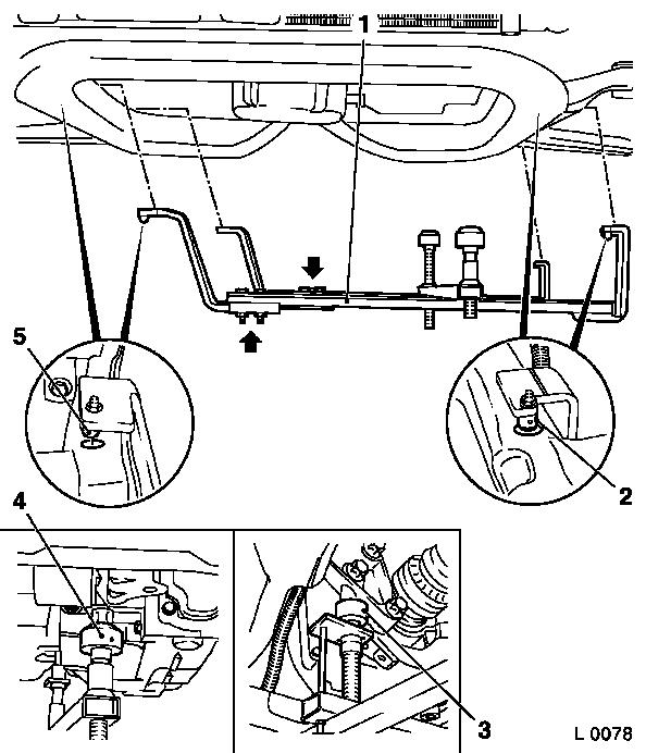
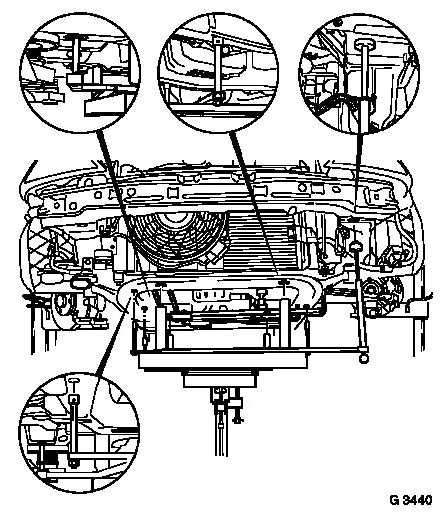
Note: For greater
clarity, the illustration shows the front axle body without
hydraulic jack and centring mount.
Remove
Remove six rear fastening bolts (4) on left and right. Remove
front fastening bolts on right (1) and left (3). Remove centre
fastening bolts (2).
Carefully lower front axle body with entire drive unit, steering
gear and radiator – thereby ensuring that no attaching parts
are damaged.
|
|
Caution
Ensure the threads of the captive nuts move freely before
installing front axle body with drive unit, steering gear and
radiator, replace captive nuts if necessary.
Install
|
Carefully guide front axle body with entire drive unit, steering
gear and radiator into engine compartment and position free of play
on chassis – thereby ensuring that no attaching parts are
damaged.
Attach front axle body to vehicle underbody with new fastening
bolts (1- 4) – tightening torque 90 Nm / 66.5 lbf. ft. +
45° + 15°.
|
|
Caution
Installing the front axle body using an impulse or impact
screwdriver is not permissible. Note dissimilar bolt lengths and
washers.
Install
Attach right engine damping block bracket to engine damping
block support – tightening torque 55 Nm / 41 lbf. ft.
Attach left engine damping block bracket to engine damping block
support – tightening torque 55 Nm / 41 lbf. ft.
For version with air conditioning:
Connect refrigerant line – tightening torque 20 Nm / 15
lbf. ft.
Attach refrigerant line to receiver-dryer – tightening
torque 20 Nm / 15 lbf. ft.
Remove
Remove Engine Mount KM-6001-A and Engine Support KM-6173.
Install
For version with manual transmission:
Attach shift guide using clamp to shift rod – it is only
tightened after the transmission shift linkage is adjusted.
Install front exhaust pipe with catalytic converter and centre
muffler.
Connect ground cable for cooling module control unit to
body.
Connect wiring harness plug to cooling module control unit and
lock.
Install lower engine splash guard.
Install axle shafts – see operation "Axle Shaft, Remove
and Install" in group "E".
Attach swing arms on both sides to spring strut support tube
with new fastening nuts – counterhold with op-ended spanner
at two flattened surfaces – tightening torque 65 Nm / 48 lbf.
ft.
Install front panelling – see operation "Front Panelling,
Remove and Install" in group "A".
Attach front wheels – tightening torque 110 Nm / 81 lbf.
ft.
For version with manual transmission: Attach pressure connection
for hydraulic clutch actuator to manual transmission.
For version with automatic transmission: Clip selector actuator
cable in counterpart and slide in retaining clamp. Attach selection
lever cable to actuation lever.
Attach coolant hoses – ensure correct seating. Route
steering cable bundle and attach.
For version with automatic transmission – connect
transmission wiring harness plug.
Connect wiring harness plug to engine control unit and lock.
Attach wiring harness plug to intake manifold pressure sensor
and tank vent valve.
Connect grey multiplug and twist-connection multiplug.
Attach brake servo vacuum line and vacuum hose for intake pipe
pressure sensor to intake manifold.
Attach tank vent valve hose to throttle valve body.
Attach fuel lines to fuel distributor pipe – tightening
torque 15 Nm / 11 lbf. ft.
For Z 16 YNG: Attach CNG low pressure line to CNG distributor
pipe - see operation "CNG Low Pressure Line, Remove and
Install"
If present: allow guide for cruise control Bowden cable to
engage into bracket and connect cruise control Bowden cable onto
ball head. Install guide for accelerator Bowden cable into bracket
and insert retaining clamp behind intermediate washer. Clip ball
socket for accelerator Bowden cable to ball head – ensure
that retainer engages.
Install air cleaner housing – see illustration "Air Ducts
X 14 XE, Z 14 XE, X 16 XEL, Z 16 XE, Z 16 YNG" or "Air Ducts X 18
XE1, Z 18 XE, Z 18 XEL".
Attach battery support to body- tightening torque 15 Nm / 11
lbf. ft.
Install battery and fasten to battery support.
Coat new clamp bolt for steering column intermediate shaft with
screw locking compound (red). Attach intermediate shaft to steering
column – tightening torque 22 Nm / 16.2 lbf. ft.
Connect battery electrically.
For version with AC: Charge AC – see operation "Air
Conditioning, Evacuate and Charge" in group "D".
For version with manual transmission: Bleed hydraulic clutch
– see operation "Hydraulic Clutch Actuator, Bleed
(F13/F17/F18/F23)" in group "K".
Adjust shift mechanism – see operation "Transmission Shift
Linkage, Adjust (F13/F17/F18)" in group "K".
 Inspect
Charge cooling system – see operations "Cooling System,
Charge and Bleed" and "Cooling System, Check for Leaks".
|
