|
Cylinder Head, Remove and Install
Caution
Remove cylinder head from cold engine only (room
temperature).
Cable ties and clips which are released or detached for removing
the cylinder head must be replaced in the same position during the
installation procedure.
 Remove Remove
Disconnect ground cable from battery.
For Z 20 LET engine: Remove air intake pipe – see
illustration "Air Duct (Z 20 LET)". Remove ignition module wiring
harness plug.
|
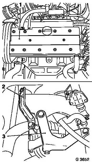
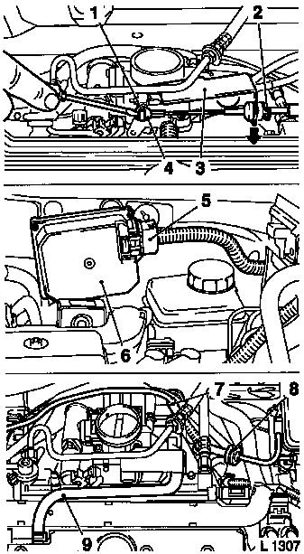
Remove ignition cable cover (1) from cylinder head cover.
Remove air cleaner housing – see illustration "Air Duct (X
20 XEV, X 20 XER)" or illustration "Air Duct (Z 20 LET)",
respectively.
Remove ribbed V-belt – see operation "Ribbed V-belt,
Remove and Install (without Air Conditioning)" or "Ribbed V-belt,
Remove and Install (with Air Conditioning)".
Remove alternator support (2) from intake manifold and
alternator.
Remove alternator shackle (3) from alternator, intake manifold
and coolant flange – swing alternator to rear.
|
|
Remove front right wheel and lower engine splash guard.
Open coolant drain bolt – collect escaping coolant.
|
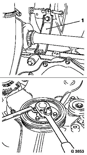
Detach intake manifold support (1) from intake manifold and
release from cylinder block – swing support to one side.
For Z 20 LET engine: Remove vacuum reservoir bracket from intake
manifold. Remove start-up catalytic converter from exhaust
manifold.
Detach front exhaust pipe from exhaust manifold.
Remove ribbed V-belt tensioner – see operation "Ribbed
V-belt tensioner, Remove and Install (without Air Conditioning)" or
"Ribbed V-belt tensioner, Remove and Install (with Air
Conditioning)".
Remove torsional vibration damper – counterhold at
fastening bolt of toothed belt drive gear.
|
|
Note: The drive unit
must be aligned to the front axle body using KM-6173 and KM-6001-A
in order to ensure correct alignment of the drive unit after
releasing the fastening bolts for the right and left engine damping
blocks. The attachment of KM-6173 and KM-6001-A is described in the
following.
 Install
|
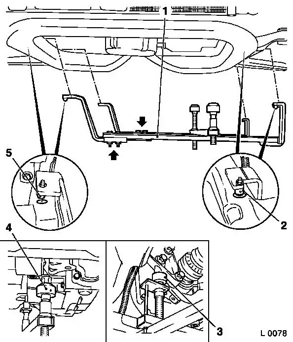
Attach KM-6173 (3) to front axle body – screw up support
bearing (2) until pin is seated flush in mount (1) on cylinder
block.
|
|
|
Release fastening bolts (arrows) for adjustment rails on
KM-6001-A (1).
Insert KM-6001-A as illustrated – pins (2) and (5) must
sit in guide holes of front axle body.
Tighten fastening bolts for adjustment rails.
Screw up front support bearing (4) and rear support bearing (3)
until contact is made with guide pins of front engine damping block
and rear engine damping block bracket – the guide pins must
seat free from play in the support bearings.
|
|
Remove
For Z 20 LET engine: Remove throttle body – see operation
"Throttle Body, Remove and Install (Z 20 LET)".
|
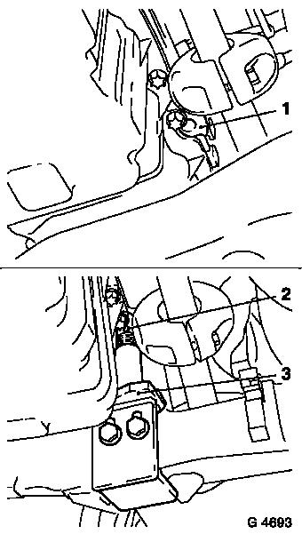
Lift retainer for accelerator Bowden
cable (1) with screwdriver and remove ball socket for accelerator
Bowden cable (4) from ball head. Detach retaining clamp (2) and
pull guide for accelerator Bowden cable out of Bowden cable bracket
(3) in direction of arrow and lay aside.
|
For version with electronic cruise control:
|
|
Remove shackle for cruise control Bowden cable from ball head
and guide for cruise control Bowden cable from Bowden cable bracket
– see operation "Cruise Control – Bowden Cable, Remove
and Install".
|
|
Disconnect wiring harness plug (5) from control unit / actuator
(6) and remove control unit / actuator from bracket – 3
fastening bolts.
|
Remove engine vent hose (9) from cylinder head cover.
Remove brake servo vacuum line (8) from intake manifold.
Remove hose for tank vent valve (7) from throttle body.
|
|
Reduce fuel pressure with Pressure Tester KM-J-34730-91 via
testing port – collect escaping fuel in suitable container
– observe safety regulations and national legislation.
|
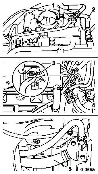
Detach fuel return line (1) from Bowden cable bracket and remove
fuel feed line (2) from fuel distributor pipe and lay aside to
rear.
For Z 20 LET engine: Detach fuel lines from fuel distributor
pipe and fuel pressure regulator.
Remove coolant hoses (3) from thermostat housing and (4) from
front coolant pipe.
Detach coolant hose (5) from coolant flange.
|
|
|
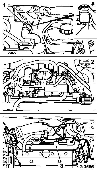
Release coolant hose (1) in direction of arrow and detach from
heater.
Detach coolant hose (2) from throttle body.
Detach or disconnect all wiring connections which are connected
to the plug strip (3) or cable bundle and place out of way –
note cable routing.
Detach plug strip from injectors and place to one side.
Remove upper part of toothed belt cover – see operation
"Toothed Belt Cover – Upper Part, Remove and Install".
|
|
|
Remove right engine damping block (1) with engine damping block
bracket.
Remove lower part of toothed belt cover – see operation
"Toothed Belt Cover – Lower Part, Remove and Install".
Caution
Before removing toothed belt – set engine to 60°
before TDC mark.
Remove
Remove cylinder head cover – see operation "Cylinder Head
Cover, Remove and Install".
Remove camshaft pulleys – see operation "Camshaft Pulleys,
Remove and Install".
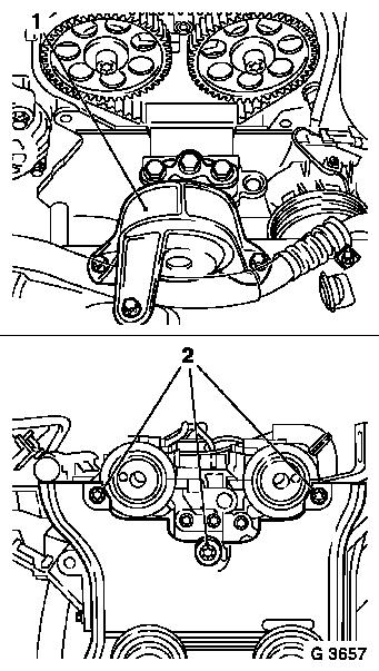
Remove camshaft sensor from cylinder head. Remove fastening
bolts (2) of rear toothed belt cover from cylinder head.
|
|
Remove exhaust camshaft – see operation "Camshafts, Remove
and Install".
|
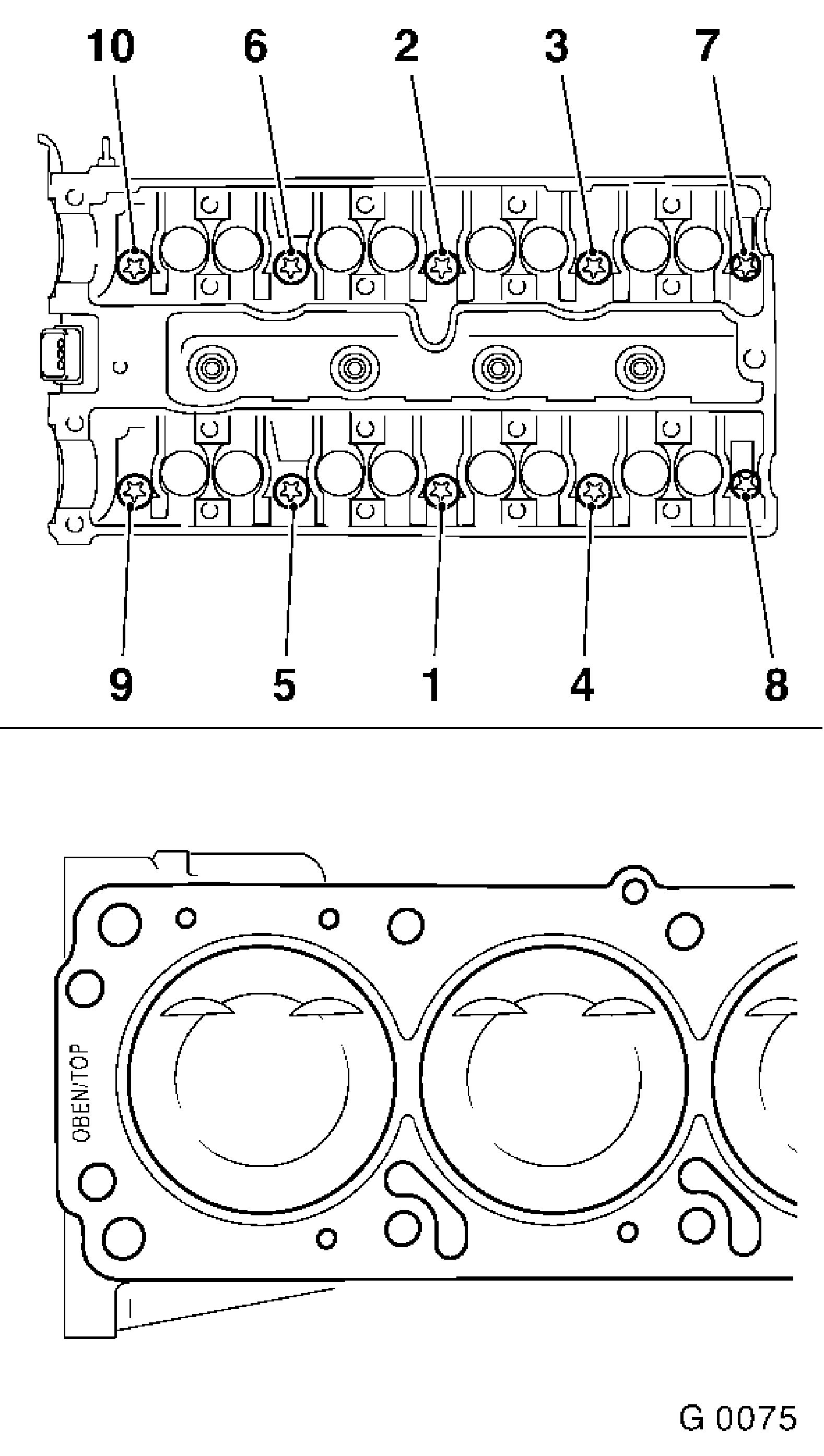
Loosen cylinder head bolts in order shown with KM-2355, first
1/4 then 1/2 turn and remove.
Remove cylinder head.
 Clean Clean
Clean sealing surfaces and bore holes and remove gasket
residue.
 Inspect
Check cylinder head and cylinder block for plane surface –
see operations "Cylinder Head, Check for Plane Surface" and
"Cylinder Block, Check for Plane Surface".
Install
Apply new cylinder head gasket to cylinder block with
identification "OBEN/TOP" on top and towards timing side of
engine.
|
|
Place cylinder head on cylinder block.
Attach cylinder head to cylinder block with new cylinder head
bolts.
|
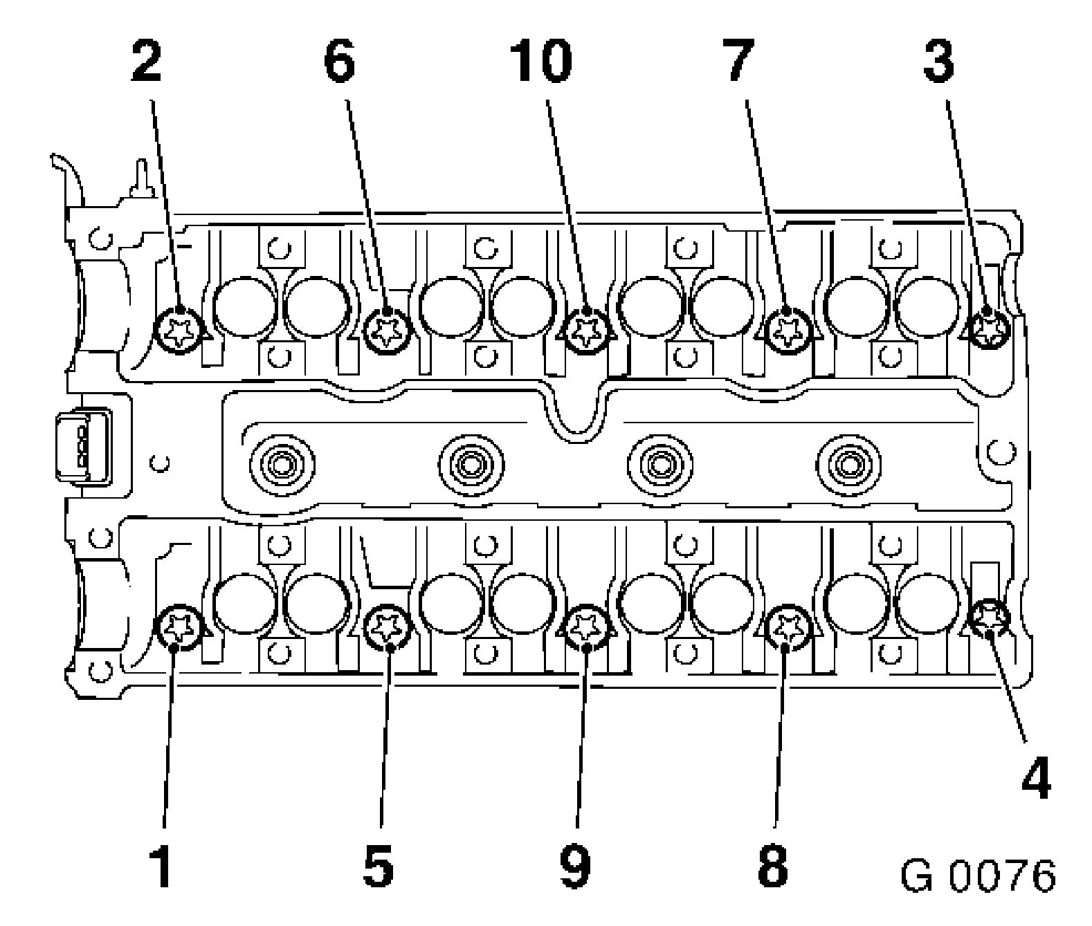
Tighten cylinder head bolts in order shown with KM-2355, MKM-610
and KM-470-B – tightening torque 25 Nm / 18 lbf. ft. +
90° + 90° + 90° + 15°.
Install exhaust camshaft. – see operation "Camshafts,
Remove and Install".
Attach rear toothed belt cover to cylinder head –
tightening torque 8 Nm / 5.9 lbf. ft.
Attach camshaft sensor to cylinder head – tightening
torque 6 Nm / 4 lbf. ft.
Install camshaft pulleys – see operation "Camshaft
Pulleys, Remove and Install".
|
|
 Adjust Adjust
Position camshafts first and then crankshaft to "1st cylinder
ignition TDC" marks (short path) and secure camshafts with KM-853
– see operation "Timing, Adjust".
Install
Install cylinder head cover – see operation "Cylinder Head
Cover, Remove and Install".
Install lower part of toothed belt cover – see operation
"Toothed Belt Cover – Lower Part, Remove and Install".
Attach engine damping block to right of side member –
tightening torque 35 Nm / 26 lbf. ft.
Attach right engine damping block bracket to engine damping
block support – tightening torque 55 Nm / 41 lbf. ft.
Install upper part of toothed belt cover – see operation
"Toothed Belt Cover – Upper Part, Remove and Install".
Connect plug strip to injectors – plug strip must engage
audibly – ensure correct seating.
Attach or connect all wiring connections which were connected to
the plug strip or cable bundle – ensure cable routing is
correct.
Attach coolant hoses to throttle body, coolant flange,
thermostat housing and front coolant pipe.
Attach and lock coolant hose to heater core.
For Z 20 LET engine: Attach fuel lines to fuel distributor pipe
and to fuel pressure regulator – tightening torque 15 Nm /
11.1 lbf. ft..
Attach fuel feed lines to fuel distributor pipe –
tightening torque 15 Nm / 11 lbf. ft.
Attach fuel return line to bracket for Bowden cables –
tightening torque 9 Nm / 6.5 lbf. ft.
Attach tank vent valve hose to throttle valve body.
Connect brake servo vacuum line to intake manifold.
Attach engine vent hose to cylinder head cover.
For version with electronic cruise control: attach control unit
/ actuator to bracket and connect wiring harness plug. Attach guide
for cruise control Bowden cable to Bowden cable bracket and shackle
for cruise control Bowden cable to ball head – see operation
"Cruise Control – Bowden Cable, Remove and Install".
Insert guide for accelerator Bowden cable into Bowden cable
bracket and connect ball socket for accelerator Bowden cable to
ball head – ensure that retainer engages.
Adjust
Pull back guide for accelerator Bowden cable until just before
throttle valve lever is operated and insert retaining clamp behind
washer.
Install
For Z 20 LET engine: Install throttle body – see operation
"Throttle Body, Remove and Install (Z 20 LET)".
Remove
Remove Mount KM-6001-A and KM-6173.
Install
Attach torsional vibration damper to toothed belt drive gear
– counterhold at fastening bolt of toothed belt drive gear
– tightening torque 20 Nm / 15 lbf. ft.
Install ribbed V-belt tensioner – see operation "Ribbed
V-belt Tensioner, Remove and Install (without Air Conditioning)" or
"Ribbed V-belt Tensioner, Remove and Install (with Air
Conditioning)".
Attach intake manifold support to intake manifold and cylinder
block – tightening torque 25 Nm / 18 lbf. ft.
For Z 20 LET engine: Attach vacuum reservoir bracket to intake
manifold – tightening torque 25 Nm / 18.5 lbf. ft. Attach
start-up catalytic converter to exhaust manifold using clamp
– tightening torque 8 Nm / 5.9 lbf. ft.
Attach front exhaust pipe with new gasket to exhaust manifold
– tightening torque – 20 Nm / 15 lbf. ft.
Close coolant drain bolt.
Attach lower engine splash guard.
Install wheel, front right – tightening torque 110 Nm / 81
lbf. ft.
Attach alternator shackle to alternator, intake manifold and
coolant flange – tightening torque 20 Nm / 15 lbf. ft.
Attach alternator support to alternator and intake manifold
– tightening torque 20 Nm / 15 lbf. ft.
Install ribbed V-belt – see operation "Ribbed V-belt,
Remove and Install (without Air Conditioning)" or "Ribbed V-belt,
Remove and Install (with Air Conditioning)".
Install air cleaner housing – see illustration "Air Duct
(X 20 XEV, X 20 XER)" or illustration "Air Duct (Z 20 LET)",
respectively.
Attach ignition cable cover to cylinder head cover –
tightening torque 3 Nm / 2.2 lbf. ft.
For Z 20 LET engine: Install air intake pipe – see
illustration "Air Duct (Z 20 LET)". Connect wiring harness plug for
ignition module.
Attach ground cable to battery.
Inspect
Charge and bleed cooling system – see operation "Cooling
System, Charge and Bleed" and "Cooling System, Check for
Leaks".
|
