|
Cylinder Head, Remove and Install (X 18 XE1)
 Remove Remove
|
Remove air cleaner housing – see illustration "Air Ducts X
18 XE1, Z 18 XE, Z 18 XEL".
Remove ribbed V-belts – see operation "Ribbed V-belts,
Remove and Install".
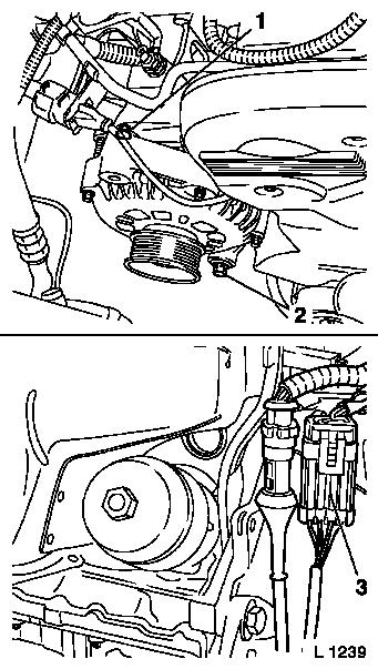
Release lower alternator fastening bolt (2).
Remove upper alternator fastening bolt (1) – twist
alternator rearwards.
Disconnect wiring harness plug for oxygen sensor (3) and place
cable out of way.
|
|
|
Disassemble or remove front right wheel and lower right engine
splash guard.
Open coolant drain bolt – collect escaping coolant.
Detach front exhaust pipe from exhaust manifold.
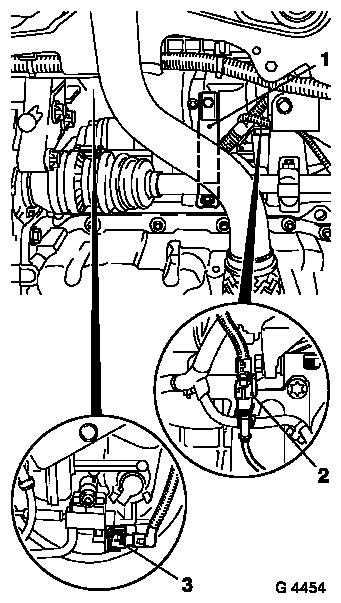
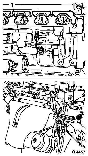
Detach intake manifold support (1) from intake manifold and
release from cylinder block – swing support to one side.
Detach or disconnect wiring harness plug for crankshaft pulse
pick-up (2) and wiring harness plug for solenoid valve for
switchover valve (3).
|
|
 Install
|
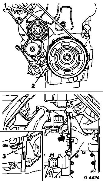
Detach ribbed V-belt tensioner (1) from alternator support.
Lever closure plug (arrow) out of opening with screwdriver.
Insert KM-911 (3) in opening and lock flywheel or drive
disc.
Detach increment disc (2) from crankshaft.
|
|
|
Note: The drive unit
must be aligned to the front axle body using KM-6173 and KM-6001-A
in order to ensure correct alignment of the drive unit after
releasing the fastening bolts for the right and left engine damping
blocks. The attachment of KM-6173 and KM-6001-A is described in the
following.
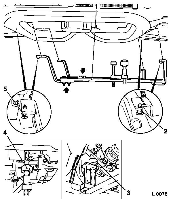
Install
Attach KM-6173 (3) to front axle body – screw up support
(2) until pins are seated flush in mount (1) on cylinder block.
|
|
Remove
|
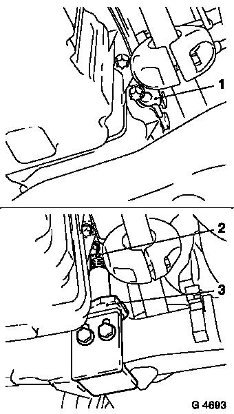
Release fastening bolts (arrows) for adjustment rails on
KM-6001-A (1).
Insert KM-6001-A as illustrated – pins (2) and (5) must
engage in guide holes of front axle body.
Tighten fastening bolts for adjustment rails.
Screw up front support bearing (4) and rear support bearing (3)
up to contact surface of engine damping block (front and rear)
– the guide pins must seat free from play in the support
bearings.
|
|
|
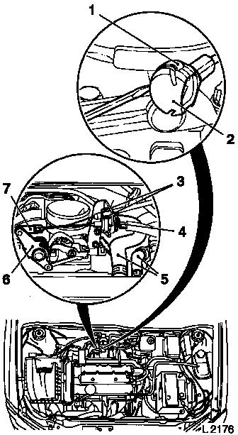
Press throttle valve lever (6) in direction of "full
acceleration" and hold in position.
Lift retainer (1) with screwdriver and remove ball socket (2)
from ball head.
If present: remove shackle for cruise control Bowden cable (7).
Compress guide for cruise control Bowden cable at the two pins (3)
and remove from bracket – lay cruise control Bowden cable
aside.
Disconnect retaining clamp (4) upwards and pull guide for
accelerator Bowden cable out of bracket and lay aside.
Remove engine vent hoses (5) from cylinder head cover.
|
|
|
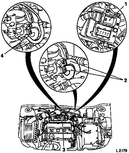
Detach or remove required cable connections, that are connected
to plug strip or cable bundle (3), and lay out of the way –
note cable routing.
Detach plug strip from injectors with wiring trough and place to
one side.
Detach wiring harness plug (1) from engine control unit.
Detach tank vent valve hose (4) from throttle body.
Detach coolant hoses (2) from throttle body – collect
escaping coolant.
|
|
|
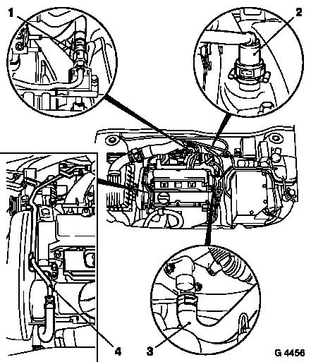
Detach coolant line or hose (4) from intake manifold, cylinder
head cover and from thermostat housing and place to one side.
Detach coolant hose (heater) (3) from intake manifold.
Reduce fuel pressure with Pressure Tester KM-J-34730-91 via
testing port – collect escaping fuel in suitable container
– observe safety regulations and national legislation.
Detach fuel feed line (1) from fuel distributor pipe.
Detach brake servo vacuum line (2) from intake manifold.
|
|
|
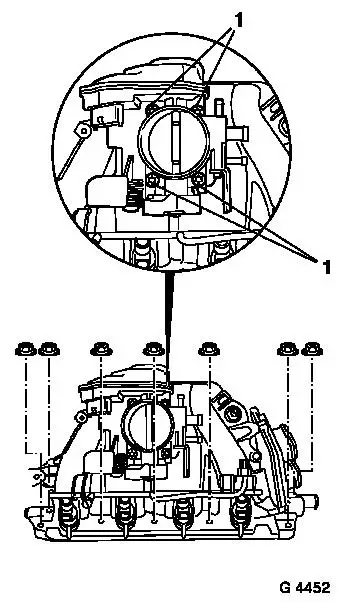
Detach rear engine transport shackle from cylinder head.
Remove fastening bolts (1) – remove throttle body from
intake manifold.
Detach intake manifold from cylinder head and remove.
|
|
|
Detach coolant hose (1) from coolant pump and from coolant
flange – if necessary release coolant pipe from cylinder
block.
Detach upper coolant hose from thermostat housing.
Remove fastening bolts (arrow) and swing oil dipstick guide tube
(2) to one side.
|
|
Remove upper part of toothed belt cover – see operation
"Toothed Belt Cover – Upper Part, Remove and Install".
Remove lower part of toothed belt cover – see operation
"Toothed Belt Cover – Lower Part, Remove and Install".
Caution
Before removing toothed belt – set crankshaft to approx.
60° before "1st cylinder TDC".
Remove
Remove toothed belt – see operation "Toothed Belt, Remove
and Install".
Remove ignition module – see operation "Ignition Module,
Remove and Install (X 18 XE1, Z 18 XE, Z 18 XEL)".
Remove cylinder head cover – see operation "Cylinder Head
Cover, Remove and Install".
Remove camshaft sprockets – see operation "Camshaft
Sprockets, Remove and Install".
Rear toothed belt cover – see operation "Toothed Belt
Cover – Rear, Remove and Install".
|
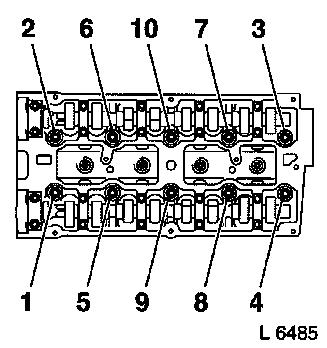
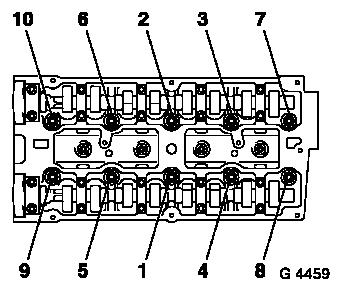
Release cylinder head bolts in illustrated sequence by first
with 1/4 turns, then 1/2 turns.
Remove cylinder head from cylinder block.
 Clean Clean
Clean sealing surfaces and remove gasket residues.
 Inspect
Check cylinder head and cylinder block for plane surface –
see operations "Cylinder Head, Check for Plane Surface" and
"Cylinder Block, Check for Plane Surface".
|
|
|
Note: If checking or
overhaul cylinder head:
Remove all attaching parts in cylinder head – see operation
"Attaching Parts – Cylinder Head, Remove and Install".
Install
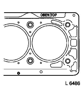
Place new cylinder head gasket on cylinder block with
identification "Oben/Top" uppermost.
If the cylinder head has been overhauled:
Install all attaching parts in cylinder head – see
operation "Attaching Parts – Cylinder Head, Remove and
Install".
|
|
|
Mount cylinder head on cylinder block and fasten with new bolts
in illustrated sequence with MKM-610 and KM-470-B –
tightening torque 25 Nm / 18.5 lbf. ft. + 90° + 90° +
90° + 45°.
Install rear toothed belt cover – see operation "Toothed
Belt Cover – Rear, Remove and Install".
Install camshaft sprockets – see operation "Camshaft
Sprockets, Remove and Install".
Install cylinder head cover – see operation "Cylinder Head
Cover, Remove and Install".
Install ignition module – see operation "Ignition Module,
Remove and Install (X 18 XE1, Z 18 XE, Z 18 XEL)".
Install toothed belt – see operation "Toothed Belt, Remove
and Install".
Install lower part of toothed belt cover – see operation
"Toothed Belt Cover – Lower Part, Remove and Install".
Install upper part of toothed belt cover – see operation
"Toothed Belt Cover – Upper Part, Remove and Install".
|
|
Attach oil dipstick guide tube bracket to cylinder head.
Attach upper coolant hose to thermostat housing.
Attach coolant hose to coolant pump connection and coolant
flange – attach coolant pipe to cylinder block if
released.
Attach intake manifold to cylinder head with new gasket and new
fastening nuts – tightening torque 20 Nm / 15 lbf. ft.
Attach throttle body with new gasket to intake manifold –
tightening torque 8 Nm / 6 lbf. ft.
Attach rear engine transport shackle to cylinder head – 25
Nm / 18.5 lbf. ft.
Attach brake servo vacuum line to intake manifold.
Attach fuel feed lines to fuel distributor pipe –
tightening torque 15 Nm / 11 lbf. ft.
Attach coolant line to intake manifold and cylinder head cover
– tightening torque 8 Nm / 6 lbf. ft.
Attach coolant hose or line to thermostat housing.
Attach coolant hoses to throttle body and intake manifold.
Attach tank vent valve hose to throttle body.
Connect wiring harness plug to engine control unit and lock.
Connect plug strip to injectors – plug strip must audibly
engage.
Connect or attach all wiring connections which are connected to
the injectors plug strip.
Attach engine vent hoses to cylinder head cover.
If present: insert guide for cruise control Bowden cable into
bracket and connect shackle for cruise control Bowden cable onto
ball head.
Install guide for accelerator Bowden cable in bracket and insert
retaining clamp behind intermediate washer. Clip ball socket for
accelerator Bowden cable to ball head – ensure that retainer
engages.
Remove
Remove Engine Support KM-6173 and Engine Mount KM-6001-A.
Install
Attach increment disc with new bolt to crankshaft –
tightening torque 95 Nm / 70 lbf. ft. + 45° + 15° –
counterhold with KM-911.
Remove Locking Tool KM-911 and insert new closure plug in
aperture.
Attach ribbed V-belt tensioner to alternator support –
tightening torque 35 Nm / 26 lbf. ft.
Attach or connect wiring harness plug for crankshaft pulse
pick-up and wiring harness plug for solenoid valve for switchover
valve.
Attach intake manifold support to intake manifold –
tightening torque 20 Nm / 15 lbf. ft.
Fasten intake manifold support to cylinder block –
tightening torque 35 Nm / 26 lbf. ft.
Attach front exhaust pipe with new gasket to exhaust manifold
– tightening torque – 20 Nm / 15 lbf. ft.
Install lower right engine splash guard.
Attach wheel to wheel hub – tightening torque 110 Nm / 81
lbf. ft.
Connect wiring harness plug for oxygen sensor.
Attach alternator to alternator shackle – tightening
torque 20 Nm / 15 lbf. ft.
Tighten lower alternator fastening bolt – tightening
torque 35 Nm / 26 lbf. ft.
Install ribbed V-belt – see operation "Ribbed V-belt,
Remove and Install".
Install air cleaner housing – see illustration "Air Ducts
X 18 XE1, Z 18 XE, Z 18 XEL".
Install engine cover.
Inspect
Charge and bleed cooling system – see operation "Cooling
System, Charge and Bleed" and "Cooling System, Check for
Leaks".
Check engine oil level and correct if necessary.
|
