|
Timing Case, Remove and Install
Note: Note differing
designs! New components for DOHC-0-petrol engines:
TN 2004 - New components in MY 2004 
- TN 2005 - Camshaft control from end of MY 2004 to MY 2005
- TN 2005 - Camshaft control from MY 2005
- TN 2005 Adjusting the phase sensor disc
- TN - 2005 Camshaft sensor
- TN 2005 - Timing chain tensioner
Note: The timing case
must be removed and installed for the operations listed in the
following:
|
1
|
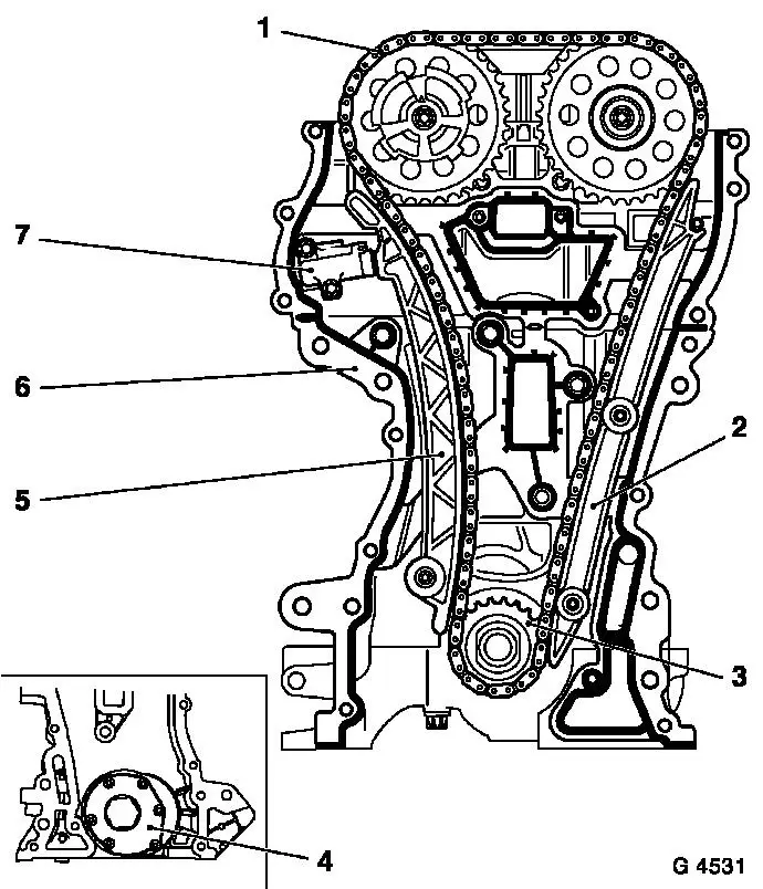
Timing Chain, Remove and Install
|
|
|
|
|
2
|
Guide Rails, Remove and Install
|
|
|
|
|
3
|
Crankshaft Sprocket, Remove and Install
|
|
|
|
|
4
|
Oil Pump, Remove and Install
|
|
|
|
|
5
|
Tension Rail, Remove and Install
|
|
|
|
|
6
|
Timing Case Gasket, Replace
|
|
|
|
|
7
|
Chain Tensioner, Remove and Install
|
|
|
 Remove Remove
Disconnect earth cable from battery.
Remove oil pan – see operation "Oil Pan, Remove and
Install".
Remove air cleaner housing with hot film mass air flow meter and
air intake cover - see illustration "Air Ducts X 12 XE" or "Air
Ducts Z 12 XE" or "Air Ducts Z 14 XEP".
Remove ribbed V-belts – see operation "Ribbed V-belts,
Remove and Install".
Remove ribbed V-belt tensioner – see operation "Ribbed
V-belt Tensioner, Remove and Install".
Remove alternator – see operation "Alternator, Remove and
Install".
Open coolant drain bolt – collect escaping coolant.
|
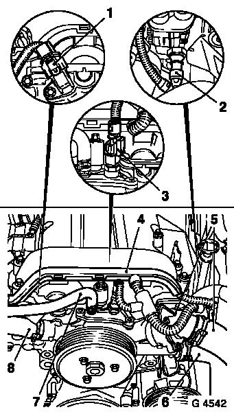
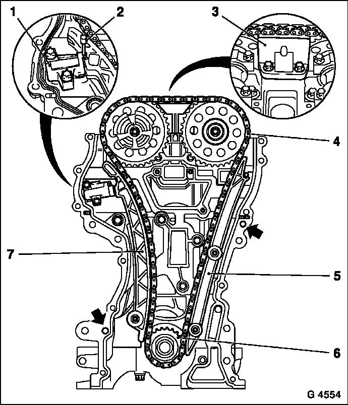
Remove thermostat housing and coolant hose (5) from coolant pump
and radiator.
Detach coolant hoses (6), (7) and (8) from coolant pump.
Disconnect wiring harness plug from camshaft sensor (1), oil
pressure switch (2) and coolant temperature sensor (3).
Unclip wiring trough (4) from cylinder head cover and lay aside
to rear.
|
|
|
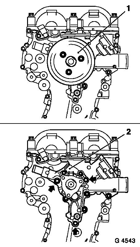
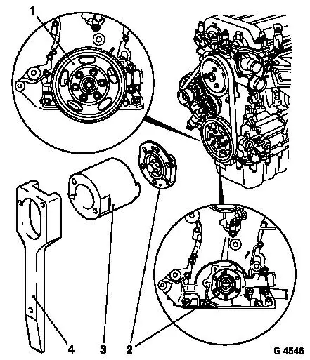
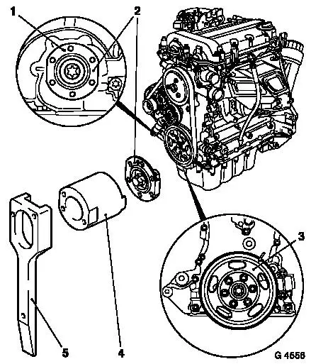
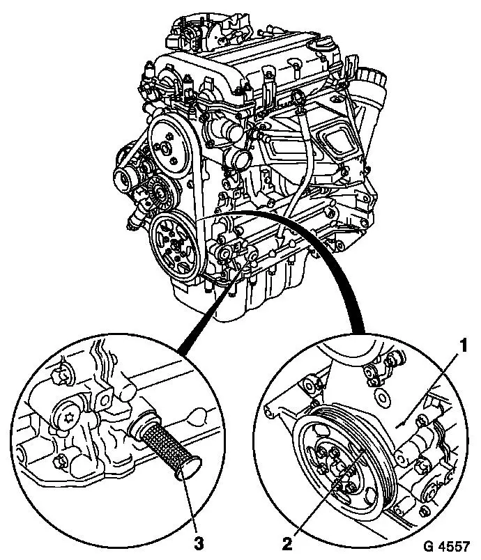
Detach pulley (1) from coolant pump.
Caution
Note guide sleeves when removing coolant pump.
Remove
Detach coolant pump (2) from timing case and note dissimilar
length bolts (arrows = short bolts).
|
|
For version with air conditioning: Detach compressor from timing
case and cylinder block and lay aside to front.
Caution
The air conditioning system remains sealed.
Remove
|
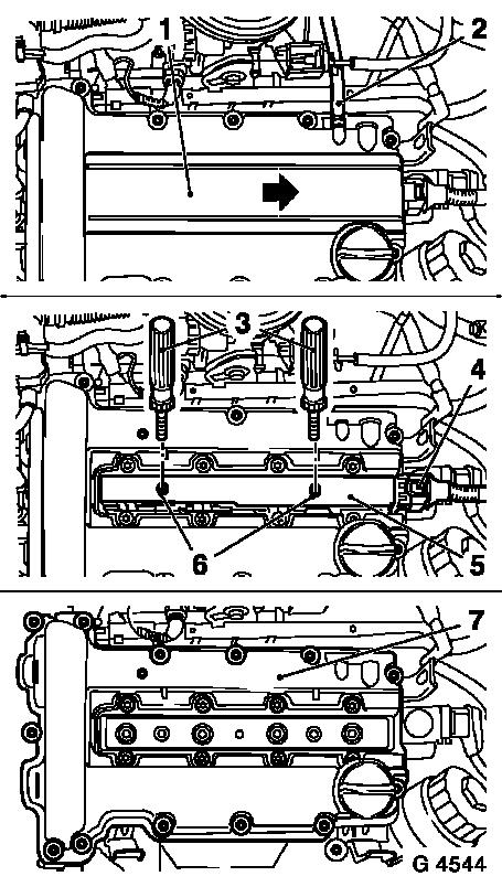
Detach engine vent hose (2) from cylinder head cover.
Disconnect wiring harness plug (4) from ignition module.
Detach ignition module cover (1) from cylinder head cover in
direction of arrow.
Remove fastening bolts (6) and disconnect ignition module (5)
from spark plugs using KM-6009 (3) – do not tilt as otherwise
the spark plug connectors can be damaged.
Detach cylinder head cover (7) from cylinder head.
|
|
 Adjust Adjust
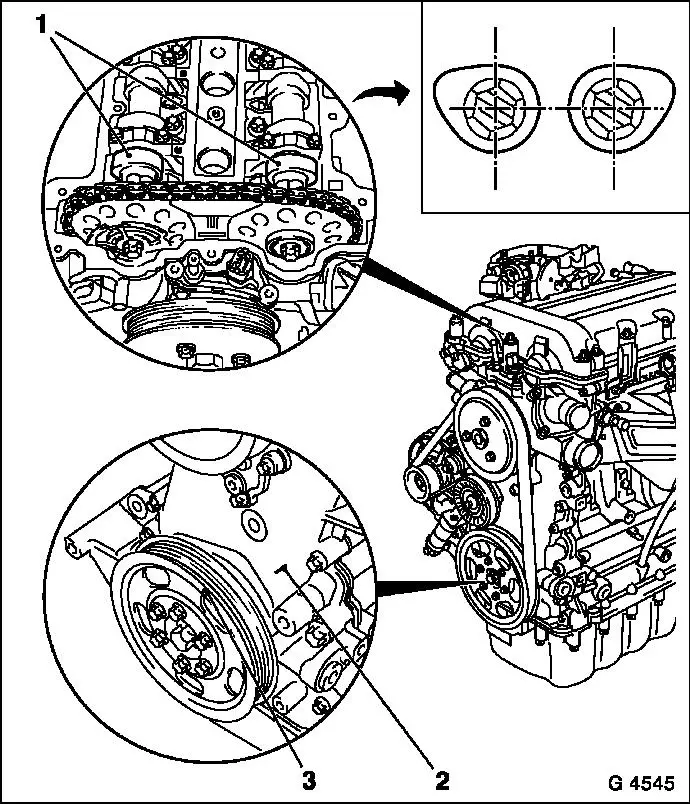
Turn crankshaft slowly and smoothly.
Move crankshaft in direction of engine rotation to just before
"1st Cylinder TDC" position using fastening bolt for crankshaft
hub.
 Inspect
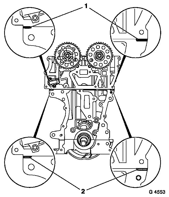
|
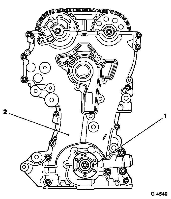
The mark (3) on the crankshaft pulley is located just before the
lug (2) on the timing case.
In this position the cams for the 1st cylinder (1) are located
just before "TDC" (both cams point outwards).
|
|
Remove
|
Remove crankshaft belt pulley (1) – counterhold at the
fastening bolt for the crankshaft hub.
Release fastening bolt for crankshaft hub (2) (do not remove)
– attach KM-6013 (3) for this and counterhold with KM-956
(4).
|
|
|
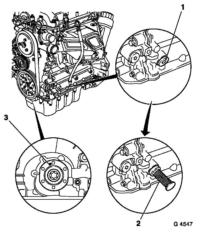
Detach closure bolt (1) for cylinder block base plate.
Adjust
Insert KM-952 (2) into opening and, at the same time, at the
fastening bolt of the crankshaft hub, slowly further turn
crankshaft in the engine rotational direction until KM-952 engages
in base plate of cylinder block or crankshaft webs to the stop.
Inspect
In this position, the marking (3) on the crankshaft hub must
point upwards.
|
|
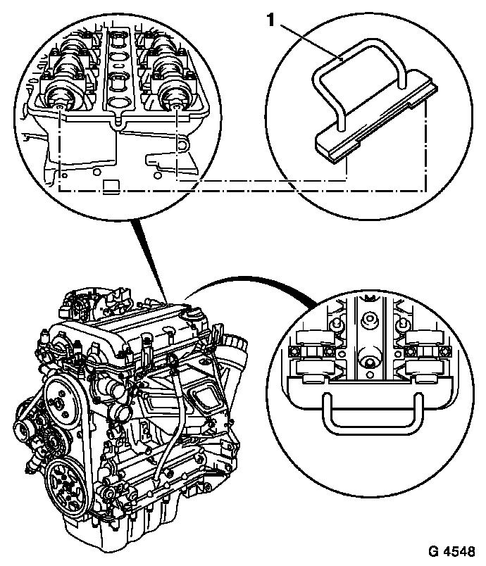
 Install
|
Insert KM-953 (1) into camshaft – KM-953 must engage in
grooves of camshafts to the stop.
|
|
Remove
|
Remove crankshaft hub (1).
Detach timing case (2) from cylinder head, cylinder block and
cylinder head base plate.
|
|
|
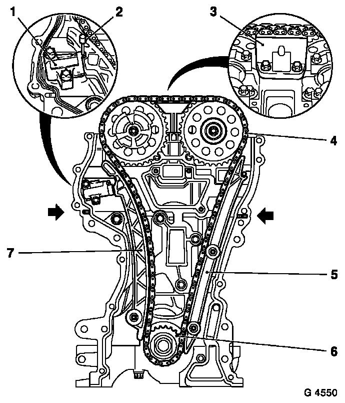
Push back chain tensioner (1) and lock with KM-955-1 (2).
Remove sliding rail (3), guide rail (5) and tension rail
(7).
Timing chain (4), drive sprocket (6) and timing case gasket.
 Clean Clean
Clean sealing surfaces and remove gasket remnants.
Caution
If a two-part timing case gasket has been used, sealant must be
removed in the vicinity of the cylinder head gasket (arrows).
|
|
Remove
|
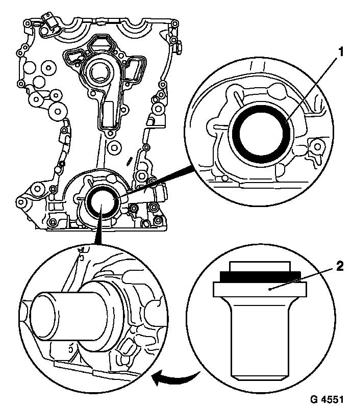
Lever seal ring (1) out of timing case with suitable tool.
Caution
Do not damage sealing surfaces.
Clean
Clean sealing surfaces and remove gasket remnants.
Install
Slide seal ring on KM-960 (2).
Drive seal ring flush into timing case using KM-960.
|
|
Remove
|
Insert new coolant pump (1) seal into timing case.
Caution
Ensure guide sleeves (arrows) are seated correctly.
Install
Attach coolant pump to timing case with short bolts (2) –
tightening torque 8 Nm / 6 lbf. ft.
|
|
Caution
|
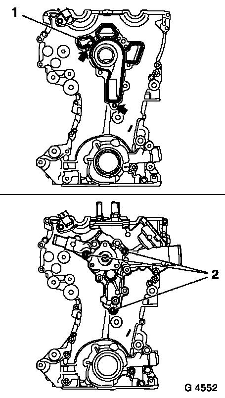
Cut off elastomer projections of cylinder head gasket (1) so
they are flush and replace with an approx. 1 mm thick bead of
silicon sealant (grey) (2).
The bead of silicon sealant (grey) (2) can be applied directly
if there is no protruding elastomer.
The timing case must be mounted within 10 minutes of applying
the silicon sealant (grey).
|
|
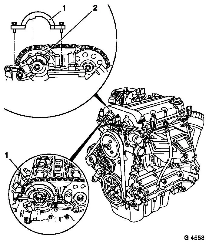
Install
|
Install new timing case gasket – ensure correct seating of
guide sleeves (arrows). Place drive gear (6) onto crankshaft.
Install timing chain (4) on drive sprocket and camshaft
sprockets. Thereby ensure that tension side (exhaust side) of
timing chain is tensioned.
Attach tension rail (7) to cylinder block – tightening
torque 20 Nm / 15 lbf. ft.
Attach guide rail (5) to cylinder block – tightening
torque 8 Nm / 6 lbf. ft.
Attach sliding rail (3) to cylinder head – tightening
torque 8 Nm / 6 lbf. ft.
Remove
Remove KM-955-1 (2) out of chain tensioner (1).
|
|
Caution
Observe installation sequence.
Install
Attach timing case.
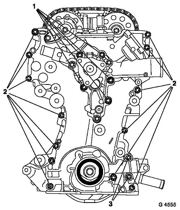
Installation sequence:
- Hand-tighten all fastening bolts.
- Attach coolant pump/ timing case fastening bolts (1) to
cylinder head and cylinder block – tightening torque 8 Nm / 6
lbf. ft.
- Attach timing case fastening bolts (2) and (3) to cylinder
head, cylinder block and to base plate of cylinder block.
Attach timing case with M6 fastening bolts (2) to cylinder head,
cylinder block and to base plate of cylinder block- tightening
torque 8 Nm / 6 lbf. ft.
Attach timing case with M10 fastening bolts (3) to cylinder
block, and base plate of cylinder block- tightening torque 35 Nm /
26 lbf. ft.
|
|
Caution
Remove KM-952 and KM-953 – Special Service Tools must not
be used to counterhold.
|
Ensure installation position of crankshaft hub (2) is correct
– mark (1) must point upwards.
Install
Attach crankshaft hub to crankshaft with new fastening bolts
– attach KM-6013 (4) for this operation and counterhold with
KM-956 (5) – tightening torque 150 Nm / 111 lbf. ft. +
45°.
Attach crankshaft belt pulley (3) to crankshaft hub –
counterhold at the fastening bolts for the crankshaft hub –
tightening torque 8 Nm / 6 lbf. ft.
|
|
Adjust
Move crankshaft approx. 720° in direction of engine rotation
to just before "1st Cylinder TDC" position using fastening bolt for
crankshaft hub.
Inspect
|
The mark (3) on the crankshaft pulley is located just before the
lug (2) on the timing case.
In this position, the cams for the 1st cylinder are located just
before "TDC" (both cams point outwards).
|
|
Adjust
Turn crankshaft slowly and smoothly.
|
Insert KM-952 (3) into opening and, at the same time, at the
fastening bolt of the crankshaft hub, slowly further turn
crankshaft in the engine rotational direction until crankshaft
locking pin engages in base plate of cylinder block or crankshaft
webs to the stop.
Inspect
In this position, the mark (2) on the crankshaft pulley must be
flush with the lug (1) on the timing case.
|
|
Inspect
|
Insert KM-953 (1) into camshaft – KM-953 must engage in
grooves of camshafts to the stop.
Note: If KM-953
cannot be inserted, then a basic adjustment should be performed
– see operation "Timing, Adjust".
|
|
|
Position KM-954 (1) on the phase sensor disc (2) and attach to
timing case.
Note: If KM-954
cannot be inserted, then a basic adjustment should be performed
– see operation "Timing, Adjust".
|
|
Remove
Remove or disassemble KM-954, KM-953 and KM-952.
Install
Install closure bolt in cylinder block base plate with new seal
ring – tightening torque 60 Nm / 44 lbf. ft.
Clean
Clean sealing surfaces and remove gasket remnants.
|
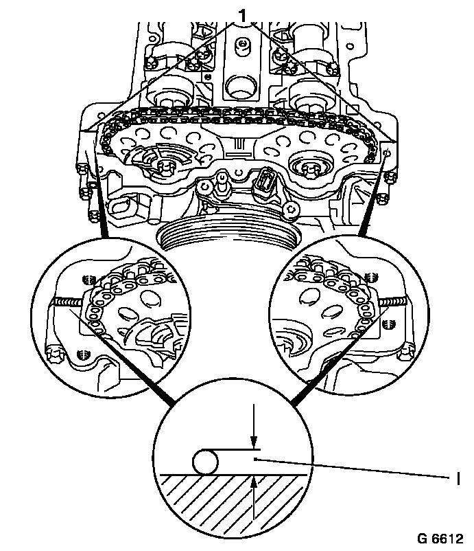
Procedure
Cut off protruding cylinder head gasket (1) flush with cylinder
head/ timing case and replace with an approx. 2 mm thick bead of
silicon sealant (grey) (dimension I).
Caution
The cylinder head cover must be mounted within 10 minutes of
applying the silicon sealant (grey).
|
|
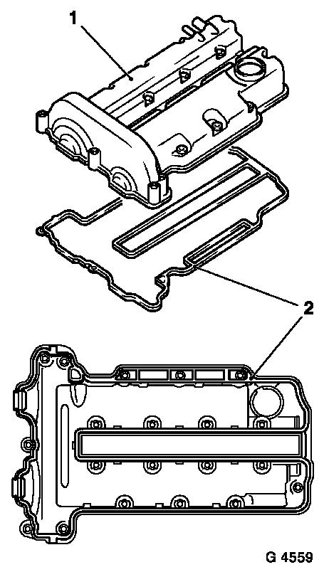
Install
|
Insert new seal (2) in cylinder head cover (1).
Attach cylinder head cover to cylinder head – tightening
torque 8 Nm / 6 lbf. ft.
Connect ignition module to spark plugs and attach to cylinder
head – tightening torque 8 Nm / 6 lbf. ft.
Attach ignition module cover to cylinder head cover.
Connect wiring harness plug to ignition module.
Attach engine vent hose to cylinder head cover.
|
|
For version with air conditioning: Attach compressor to timing
case and cylinder block – tightening torque 20 Nm / 15 lbf.
ft.
Attach pulley to coolant pump – tightening torque 20 Nm /
15 lbf. ft.
Attach or connect wiring harness plug to coolant temperature
sensor, camshaft sensor and to oil pressure switch.
Clip wiring trough to cylinder head cover.
Attach coolant hoses to coolant pump.
Attach upper coolant hose to radiator and attach thermostat
housing to coolant pump with new gasket – tightening torque 8
Nm / 6 lbf. ft.
Install alternator – see operation "Alternator, Remove and
Install".
Install ribbed V-belt tensioner – see operation "Ribbed
V-belt Tensioner, Remove and Install".
Install ribbed V-belt – see operation "Ribbed V-belt,
Remove and Install".
Install air cleaner housing with hot film mass air flow meter
and air intake cover - see illustration "Air Ducts X 12 XE" or "Air
Ducts Z 12 XE" or "Air Ducts Z 14 XEP".
Install oil pan – see operation "Oil Pan, Remove and
Install".
Connect earth cable to battery.
Inspect
Charge cooling system – see operations "Cooling System,
Charge and Bleed" and "Cooling System, Check for Leaks".
|
