|
Intake Manifold, Remove and Install (X 14 XE, X 16
XEL)
 Remove Remove
|
Remove engine cover.
Remove air cleaner housing – see illustration "Air Ducts X
14 XE, Z 14 XE, X 16 XEL, Z 16 XE".
Remove ribbed V-belts – see operation "Ribbed V-belts,
Remove and Install".
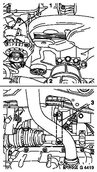
Release lower alternator fastening bolt (2).
Remove alternator shackle (1) and twist alternator
rearwards.
Detach intake manifold support (3) from intake manifold and
release from cylinder block – swing support to one side.
|
|
|
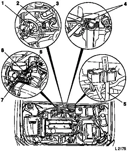
Lift retainer (8) with screwdriver and remove ball socket (7)
from ball head. Disconnect retaining clamp (6) and pull guide for
accelerator Bowden cable out of bracket in direction of arrow and
lay aside.
Detach engine vent hoses from cylinder head cover.
Detach hose for intake pipe pressure sensor (5) from intake
manifold.
Remove hose for tank vent valve (3) from throttle body.
Detach brake servo vacuum line (2) from intake manifold.
Detach vacuum hose (1) from fuel pressure regulator.
Detach coolant hoses (4) from throttle body – collect
escaping coolant.
|
|
|
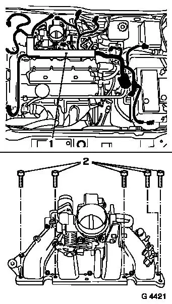
Detach or disconnect all wiring connections which are connected
to the plug strip (1) and place out of way – note cable
routing.
Detach plug strip from injectors with wiring trough and place to
one side.
Remove fastening bolts (2) and remove intake manifold from
intake manifold flange.
Transfer attaching parts when replacing intake manifold.
 Clean Clean
Clean sealing surface and remove sealant residues.
|
|
 Install
Attach intake manifold to intake manifold flange with new gasket
– tightening torque 8 Nm / 6 lbf. ft.
Connect plug strip to injectors with wiring trough – plug
strip must audibly engage.
Attach or connect all wiring connections – ensure cable
routing is correct.
Attach coolant hoses to throttle body.
Attach brake servo vacuum line to intake manifold.
Connect vacuum hose to fuel pressure regulator.
Attach hose for intake pipe pressure sensor to intake
manifold.
Attach tank vent valve hose to throttle body.
Attach engine vent hose to cylinder head cover.
Install guide for accelerator Bowden cable in bracket and insert
retaining clamp behind intermediate washer. Clip ball socket for
accelerator Bowden cable to ball head – ensure that retainer
engages.
Attach intake manifold support to intake manifold –
tightening torque 20 Nm / 15 lbf. ft.
Fasten intake manifold support to cylinder block –
tightening torque 35 Nm / 26 lbf. ft.
Attach alternator shackle to coolant flange, intake manifold and
alternator – tightening torque 20 Nm / 15 lbf. ft.
Tighten lower alternator fastening bolt – tightening
torque 35 Nm / 26 lbf. ft.
Install ribbed V-belt – see operation "Ribbed V-belt,
Remove and Install".
Install air cleaner housing – see operation illustration
"Air Ducts X 14 XE, Z 14 XE, X 16 XEL, Z 16 XE".
Install engine cover.
 Inspect
Charge and bleed cooling system – see operation "Cooling
System, Charge and Bleed" and "Cooling System, Check for
Leaks".
|
