|
Multi-plate Clutch C3, Freewheel F3 and Brake Band
B3, Remove and Install (AF 20)
 Remove Remove
Remove transmission – see operation "Transmission, Remove
and Install (AF 20)". Secure converter against falling out.
|
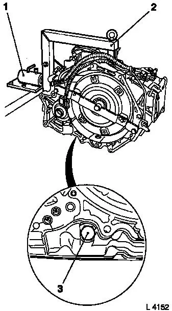
Attach transmission to KM-694-A (2). Attach assembly to KM-113-2
(1).
Remove fluid drain bolt (3), drain transmission fluid and
collect for damage diagnosis – see operation "Transmission
Fluid Condition, Check (AF 13-II/AF 17/AF 20/AF 22)".
Remove converter and fluid pump seal ring – see operation
"Converter and/or Fluid Pump Seal Ring, Replace (AF 13-II/AF 17/AF
20/AF 22)".
|
|
|
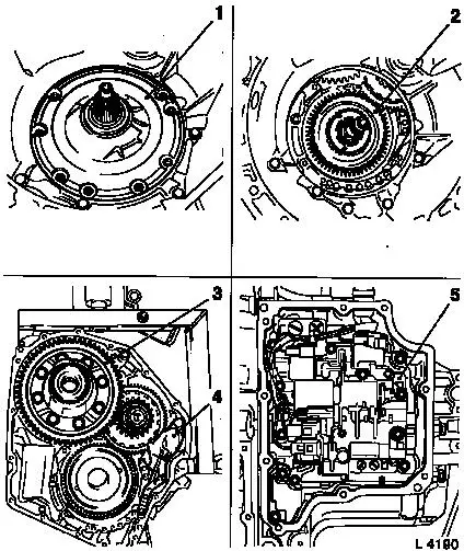
Remove fluid pump assembly (1) with multi-disc brake B1 and B2
– see operation "Fluid Pump Assembly with Multi-disc Brakes
B1 and B2, Remove and Install (AF 20)".
Remove freewheel F1 (2) – see operation "Freewheel F1,
Remove and Install (AF 20)".
Remove differential (3) – see operation "Differential,
Remove and Install (AF 20)".
Remove parking lock (4) – see operation "Parking Lock,
Remove and Install (AF 20)".
Remove valve body (5) – see operation "Valve Body, Remove
and Install (Transmission Removed) (AF 20)".
|
|
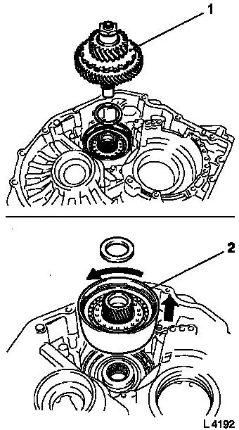
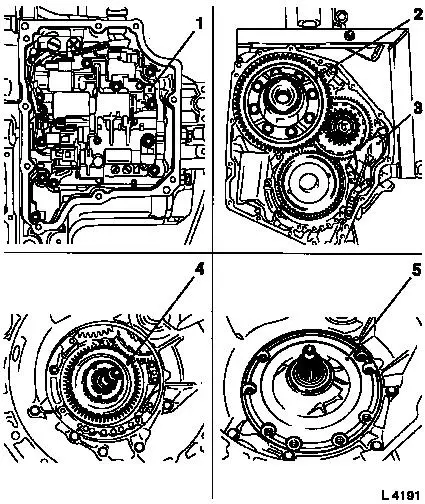
Remove planetary gear set P2 (1) – see operation
"Planetary Gear Set P2, Remove and Install (AF 20)".
|
Remove multi-plate clutch C3 (2) – turn anti-clockwise and
lift.
|
|
|
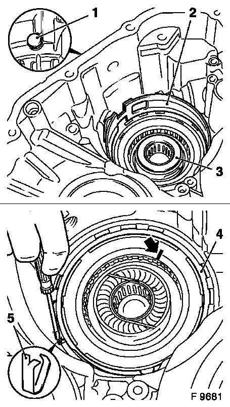
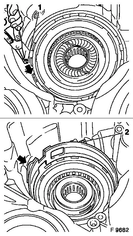
Remove anchor bolt (1) and remove brake band B4 (2) from main
housing – note installation position.
Remove thrust bearing (3) – note installation
position.
Mark upper side of freewheel F3 (arrow).
Prise out retaining ring (4) with screwdriver.
Remove freewheel F3 from main housing – pay attention to
bracket of freewheel outer race (5).
 Inspect
Check brake band B4 for damage and wear. Lay new brake band in
transmission fluid for at least 2 hours before installation.
|
|
 Install
|
Insert freewheel F3 into main housing with the mark made on
removal at top. Insert bracket for freewheel outer race (1) with
pliers – note installation position.
Insert brake band B4.
Caution
Actuation of brake band must be seated centrally in front of
piston rod (2).
Install
Attach anchor bolt with new seal ring to main housing –
tightening torque 170 Nm / 125 lbf. ft. Ensure brake band (arrow)
is seated correctly.
|
|
|
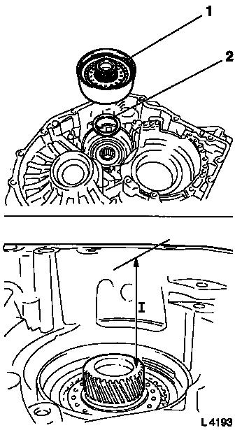
Place thrust bearing (2) onto pins in main housing – note
installation position.
Install multi-plate clutch C3 (1) – turn anti-clockwise
and insert.
 Measure
Measure distance from clutch body to upper edge of main housing
– the dimension (I) is 90.5 to 91 mm when installed
correctly.
Inspect
Turn multi-plate clutch C3 – freewheel must block
clockwise.
|
|
Install
Install planetary gear set P2 – see operation "Planetary
Gear Set P2, Remove and Install (AF 20)".
Install valve body (1) – see operation "Valve Body, Remove
and Install (Transmission Removed) (AF 20)".
|
Install parking lock (3) – see operation "Parking Lock,
Remove and Install (AF 20)".
Install differential (2) – see operation "Differential,
Remove and Install (AF 20)".
Install freewheel F1 (4) – see operation "Freewheel F1,
Remove and Install (AF 20)".
Install fluid pump assembly (5) with multi-disc brake B1 and B2
– see operation "Fluid Pump Assembly with Multi-disc Brakes
B1 and B2, Remove and Install (AF 20)".
|
|
Install fluid pump seal ring and converter – see operation
"Converter and/or Fluid Pump Seal Ring, Replace (AF 13-II/AF 17/AF
20/AF 22)". Secure converter against falling out.
|
Attach fluid drain bolt (3) with new seal ring to transmission
– tightening torque 40 Nm / 29.5 lbf. ft.
Remove transmission assembly from KM-113-2 (1) with
KM-694-A.
Remove transmission from KM-694-A (2).
Install transmission – see operation "Transmission, Remove
and Install (AF 20)".
Charge transmission fluid.
Inspect
Check and correct level of transmission fluid – see
operation "Transmission Fluid Level, Check and Correct (AF 13-II/AF
17/AF 20/AF 22)".
|
|
|
