|
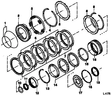
Multi-Disc Brake B3 and Freewheel F2, Remove and
Install (AF 20)
Survey
|
1
|
O-rings
|
|
2
|
Piston B3
|
|
3
|
Return spring assembly
|
|
4
|
Retaining ring
|
|
5
|
Flange
|
|
6
|
Steel plates B3
|
|
7
|
Lining plates B3
|
|
8
|
Flange
|
|
9
|
Retaining ring
|
|
|
|
10
|
Race
|
|
11
|
Thrust bearing
|
|
12
|
Freewheel inner race
|
|
13
|
Retaining ring
|
|
14
|
Freewheel F2
|
|
15
|
Thrust washer
|
|
16
|
Front ring gear
|
|
17
|
Flange
|
|
18
|
Retaining ring
|
|
19
|
Race
|
|
|
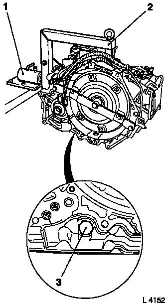
 Remove Remove
Remove transmission – see operation "Transmission, Remove
and Install (AF 20)". Secure converter against falling out.
|
Attach transmission to KM-694-A (2). Attach assembly to KM-113-2
(1).
Remove fluid drain bolt (3), drain transmission fluid and
collect for damage diagnosis – see operation "Transmission
Fluid Condition, Check (AF 13-II/AF 17/AF 20/AF 22)".
Remove converter – see operation "Converter and/or Fluid
Pump Seal Ring, Replace (AF 13-II/AF 17/AF 20/AF 22)".
|
|
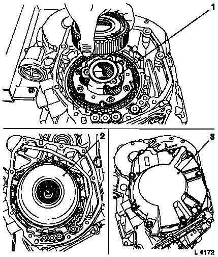
|
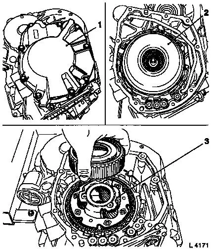
Remove rear cover (1) – see operation "Rear Cover with
Piston C1, Remove and Install (AF 20)".
Remove drive shaft assembly (2) with multi-plate clutch C1 and
C2 – see operation "Drive Shaft Assembly with Multi-plate
Clutch C1 and C2, Remove and Install (AF 20)".
Remove planetary gear set P1 (3) – see operation
"Planetary Gear Set P1, Remove and Install (AF 20)".
Remove valve body – see operation "Valve Body, Remove and
Install (Transmission Removed) (AF 20)".
|
|
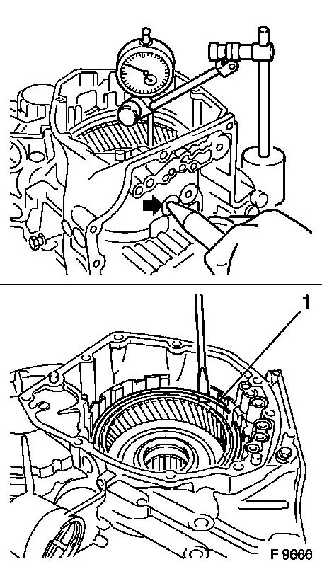
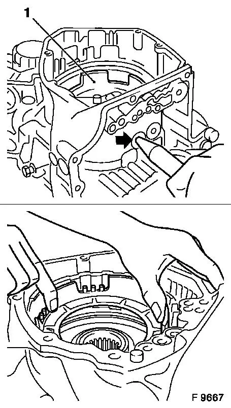
 Measure
|
Measure piston stroke of multi-disc brake B3 with Dial Gauge
MKM-571-B – place probe on plate and blow in low-pressure
compressed air (4 bar, arrow); for this, cut off the end of KM-994
in advance and insert KM-994 into bore hole. If necessary, replace
lining plates and correct piston stroke by installing a suitable
compensation flange from the "Service" division. Measurement value:
1.75 to 2.55 mm.
Measure play between piston and plate set with feeler gauge. If
necessary, replace plate set. Measurement value: 0.6 to 1.9 mm.
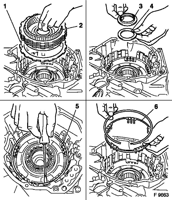
Remove
Prise out retaining ring (1) for front internal gear with
screwdriver and remove.
|
|
|
Remove assembly (2) with steel plates, lining plates and flange
(1) of multi-disc brake B3.
Remove thrust bearing (4) with race (3).
 Inspect
Check steel and lining plates for damage and wear. Place new
lining plates in transmission for at least 2 hours before
installing.
Remove
Prise out retaining ring (5) for return spring assembly (6) with
screwdriver. Remove return spring assembly.
|
|
|
Remove piston (1) for multi-disc brake B3 – blow
low-pressure compressed air (4 bar, arrow) into fluid bore; for
this, cut off the end of KM-994 in advance and insert KM-994 into
bore hole. Press out piston uniformly without tilting, assist with
pliers if necessary.
Replace seal rings on inner and outer piston.
 Clean Clean
Clean components and check for damage; replace if necessary.
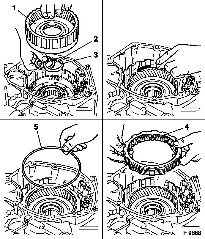
 Install
Insert piston of multi-disc brake B3 uniformly into transmission
without tilting – spring mount faces upwards.
Insert return spring assembly into spring mount of piston B3.
Install new retaining ring.
|
|
|
Insert thrust bearing (2) with race (3) – for assignment
and installation direction see illustration "Thrust Bearing
Installation". Insert assembly of front internal gear (1) with
freewheel F2 into transmission.
Inspect
Front internal gear must be able to turn anticlockwise
(arrow).
Install
Install plate set B3 (4) in transmission: Insert flange.
Alternately, insert lining plates (6 off) and steel plates (5 off)
– lugs on steel plates must be aligned with the recesses in
transmission. Insert flange. Insert new retaining ring (5) –
ensure correct seating.
|
|
Install valve body – see operation "Valve Body, Remove and
Install (Transmission Removed) (AF 20)".
|
Install planetary gear set P1 (1) – see operation
"Planetary Gear Set P1, Remove and Install (AF 20)".
Install drive shaft assembly (2) with multi-plate clutch C1 and
C2 – see operation "Drive Shaft Assembly with Multi-plate
Clutch C1 and C2, Remove and Install (AF 20)".
Install rear cover (3) – see operation "Rear Cover with
Piston C1, Remove and Install (AF 20)".
|
|
Install converter – see operation "Converter and/or Fluid
Pump Seal Ring, Replace (AF 13-II/AF 17/AF 20/AF 22)". Secure
converter against falling out.
|
Attach fluid drain bolt (3) with new seal ring to transmission
– tightening torque 40 Nm / 29.5 lbf. ft.
Remove transmission assembly from KM-113-2 (1) with KM-694-A.
Remove transmission from KM-694-A (2).
Install transmission – see operation "Transmission, Remove
and Install (AF 20)". Fill up transmission fluid
Inspect
Check and correct level of transmission fluid – see
operation "Transmission Fluid Level, Check and Correct (AF 13-II/AF
17/AF 20/AF 22)".
|
|
|
