vauxhall Workshop Repair Guides

Vauxhall Workshop Service and Repair Manuals

Multi-plate Clutch Assembly C0 and C3, Remove and Install (AF 13-II) > < Multi-plate Clutch Assembly C1, Remove and Install (AF 13-II)

Multi-plate Clutch Assembly C1, Disassemble and Assemble (AF 13-II)

Illustration

1. Seal rings (slotted)
2. Retaining ring
3. Flange
4. Steel plates C1
5. Lining plates C1
6. Housing for multi-plate clutch C1
7. Piston C1
8. Piston seal ring (inner)
9. Piston seal ring (outer)
10. Return spring assembly
11. Retaining ring
12. Thrust washer
13. Thrust washer

Object Number: 2391960  Size: DEFAULT

  Remove

Remove multi-plate clutch assembly – see operation "Multi-plate Clutch C1, Remove and Install (AF 13-II)".

  Disassemble

Remove friction washer (1) and slotted seal rings (2).

Remove retaining ring (3) for multi-plate clutch C1 with suitable screwdriver.

Remove flange (4) lining plates (5) and steel plates (6).

Install KM-J-23078-A (7) and clamp nut for tensioning in vice. Turn housing for multi-plate clutch C1 (compressing relief springs) until retaining ring is free. Remove retaining ring with KM-396 (8).

Release KM-J-23078-A and remove.

Remove return spring assembly.

Object Number: 2391961  Size: DEFAULT

  Install

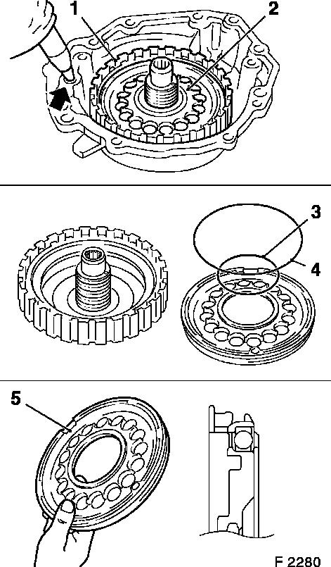
Insert housing with piston for multi-plate clutch C1 (1) in rear cover.

Caution

When inserting in rear cover, ensure that the slotted seal rings (x 4) do not get damaged.
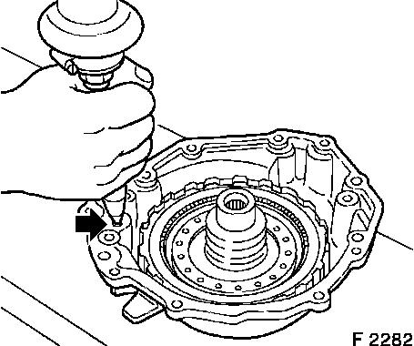
  Remove

Piston for multi-plate clutch C1 (2) – blow in low pressure (arrow) compressed air. Replace piston seal rings (3 and 4) – coat with transmission fluid before installation.
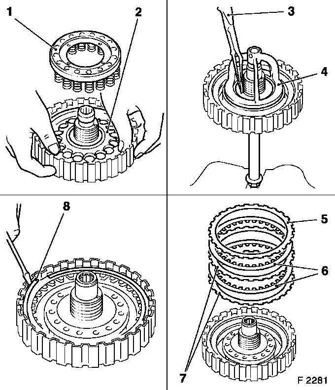
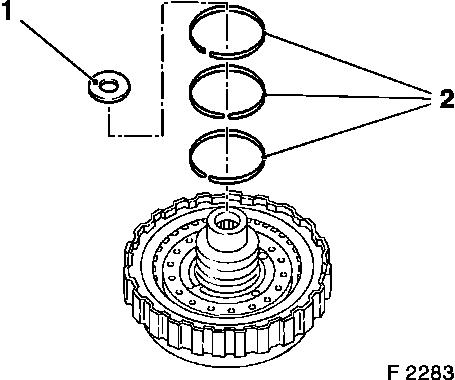
  Inspect

Lock ball of piston for multi-plate clutch C1 – shake piston (5) to check whether lock ball is movable. Check return springs assembly for damage, and replace if necessary. Check sliding surfaces of steel and lining plates for damage and wear, and replace if necessary. New lining plates must be laid in transmission fluid for at least 2 hours before installation.

Object Number: 2391962  Size: DEFAULT

  Assemble

Insert piston C1 (2) with new O-rings in housing for multi-plate clutch C1 – do not damage O-rings. Place return springs assembly (1) on piston C1 – install new retaining ring.

Attach KM-J-23078-A (4) and compress return springs – insert retaining ring with KM-396 (3). Release KM-J-23078-A and remove.

Alternately steel plate (7) and lining plate (6) on piston C1, and then flange (5)- number of steel and lining plates see "Technical Data", section "Parts List".

Insert new retaining ring (8) with screwdriver.

Object Number: 2391963  Size: DEFAULT

  Install

Insert multi-plate clutch assembly C1 in rear cover.

  Inspect

Raise piston C1 and thus check function – blow compressed air into bore on rear cover (arrow). Use KM-994.

Object Number: 2391964  Size: DEFAULT

  Install

Install slotted seal rings – x 3 (2) and thrust washer (1) with assembly grease.

Install multi-plate clutch assembly C1- see operation "Multi-plate Clutch Assembly C1, Remove and Install (AF 13-II)".

Object Number: 2391965  Size: DEFAULT


Related Literature Units
-
-
-

Multi-plate Clutch Assembly C0 and C3, Remove and Install (AF 13-II) > < Multi-plate Clutch Assembly C1, Remove and Install (AF 13-II)