|
Parking Lock, Remove and Install (AF 20)
Survey
|
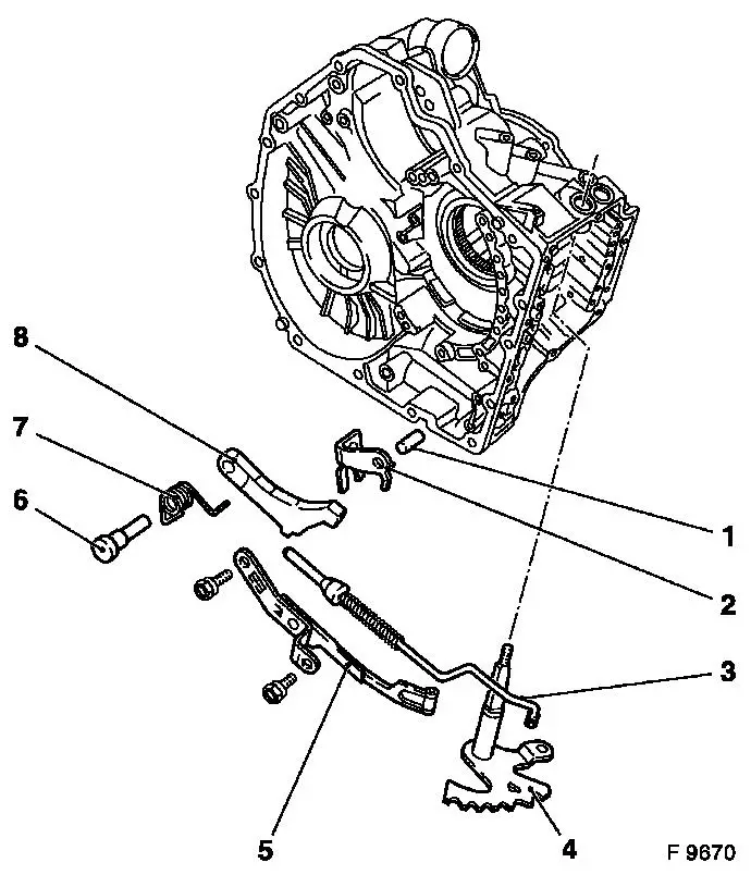
1
|
Pin
|
|
2
|
Cam plate
|
|
3
|
Actuation rod
|
|
4
|
Toothed segment
|
|
5
|
Detent spring
|
|
6
|
Shaft
|
|
7
|
Spring No. 1
|
|
8
|
Claw for parking lock
|
|
|
 Remove Remove
Remove transmission – see operation "Transmission, Remove
and Install (AF 20)". Secure converter against falling out.
|
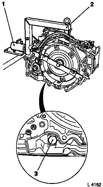
Attach transmission to KM-694-A (2). Attach assembly to KM-113-2
(1).
Remove fluid drain bolt (3), drain transmission fluid and
collect for damage diagnosis – see operation "Transmission
Fluid Condition, Check (AF 13-II/AF 17/AF 20/AF 22)".
Remove converter and fluid pump seal ring – see operation
"Converter and/or Fluid Pump Seal Ring, Replace (AF 13-II/AF 17/AF
20/AF 22)".
|
|
|
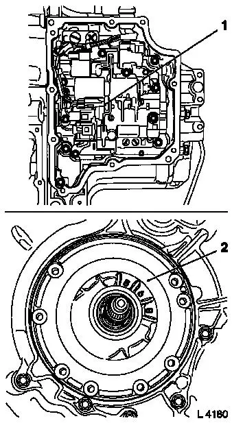
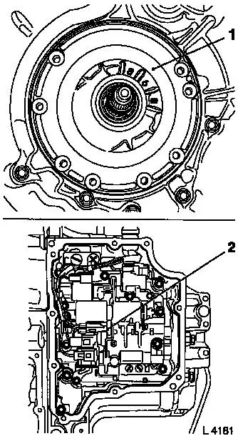
Remove valve body (1) – see operation "Valve Body, Remove
and Install (Transmission Removed) (AF 20)".
Remove fluid pump assembly (2) with multi-disc brake B1 and B2
– see operation "Fluid Pump Assembly with Multi-disc Brakes
B1 and B2, Remove and Install (AF 20)".
|
|
|
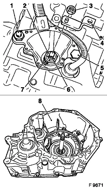
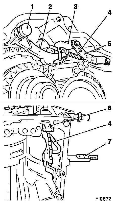
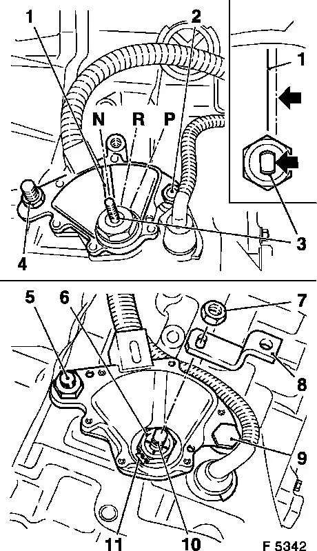
Remove actuation lever (4) from selector lever shaft (6) –
to do this, unscrew fastening nut (3).
Bend open retaining washer (7) with small screwdriver. Remove
fastening nut (2).
Remove selector lever position switch from transmission housing
– fastening bolts (1) and (5).
Remove retaining plate for solenoid valve wiring harness. Remove
selector lever position switch.
Remove auxiliary housing (8) from main housing – 15
fastening bolts, note different bolt lengths.
If necessary, detach housing parts with light taps of a plastic
hammer.
|
|
|
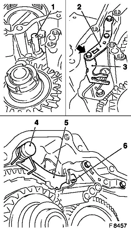
Remove fastening bolts for detent spring (5) from main housing.
Guide rear spring end (6) via notches of toothed segment (8) and
remove detent spring.
Detach actuation rod for parking lock (4) from toothed segment
(7) and remove. Pull toothed segment out of main housing.
Remove cam plate (3). Pull pin for parking lock (under cam
plate) out of main housing.
Pull shaft for parking lock (1) out of main housing. Remove
torsion spring No. 1.
Remove claw for parking lock (2).
|
|
 Install
|
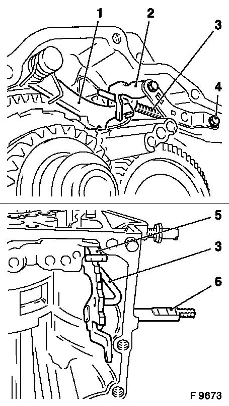
Push pin for parking lock (1) into main housing to the stop.
Attach cam plate (3) and detent spring (2) to main housing
– tightening torque 10 Nm / 7.5 lbf. ft.
Guide end of detent spring through opening in main housing to
the installation location of toothed segment. First tighten only 1
fastening bolt (arrow), so that toothed segment can be fitted.
Attach claw for parking lock (5) to mount in main housing as
well as to cam plate and torsion spring No 2 (6). Insert shaft for
parking lock and spring No 1 (4) from above into mount in main
housing – short spring end to housing inner wall, long spring
end to claw for parking lock (5). Spring No 1 keeps the claw away
from the parking lock gear.
|
|
|
Guide actuation rod for parking lock (3) through opening in main
housing to parking lock assembly – angled end is routed
between toothed segment (6) and housing wall. Insert end of
actuation rod provided with spacers between cam plate (2) and claw
(1).
Insert toothed segment (6) into main housing. Attach actuation
rod (3) in toothed segment – align lugs on rod and recesses
on toothed segment by turning toothed segment.
Attach detent spring to main housing and tighten the 2nd
fastening bolt (4) – tightening torque 10 Nm / 7.5 lbf ft.
Detent spring (5) must actuate toothed segment in the centre.
|
|
 Clean Clean
Remove gasket residue and carefully clean sealing surfaces of
main and auxiliary housing – ensure that no gasket residue
falls into the transmission housing.
Install
|
Coat sealing surface (2) with sealing compound. Attach auxiliary
housing (1) to main housing – 15 fastening bolts, note
different bolt lengths.
Torque
Auxiliary housing to main housing – 30 Nm / 22 lbf.
ft.
|
|
 Adjust Adjust
|
Place selector lever position switch onto selector lever shaft
(3) from above – attach fastening nut (6) with retaining
plate to selector lever shaft – tightening torque 8 Nm / 6
lbf ft. Secure fastening nut with retaining plate (11). Insert
fastening bolts (2) and (4) for selector lever position switch
– do not tighten yet. Place selector lever shaft into neutral
position using pliers – turn back to the right to the stop
and then 2 notches ("P", "R", "N"). Turn selector lever position
switch so that the flattened surface of the selector lever shaft
(arrows) runs parallel to the split (1) on the housing of the
switch.
Install
Attach fastening bolts (5) and (9) – tightening torque 25
Nm / 18 lbf ft. Attach actuation lever (8) to selector lever shaft
(10) with fastening nut (7) – tightening torque 16 Nm / 12
lbf ft.
Note: Final
adjustment of the selector lever position switch takes place after
installing transmission – see operation "Selector Lever
Position Switch, Adjust (AF 13-II/AF 17/AF 20/AF 22)".
|
|
Install
|
Install fluid pump assembly (1) with multi-disc brake B1 and B2
– see operation "Fluid Pump Assembly with Multi-disc Brakes
B1 and B2, Remove and Install (AF 20)".
Install valve body (2) – see operation "Valve Body, Remove
and Install (Transmission Removed) (AF 20)".
Install fluid pump seal ring and converter – see operation
"Converter and/or Fluid Pump Seal Ring, Replace (AF 13-II/AF 17/AF
20/AF 22)". Secure converter against falling out.
|
|
|
Attach fluid drain bolt (3) with new seal ring to transmission
– tightening torque 40 Nm / 29.5 lbf. ft.
Remove transmission assembly from KM-113-2 (1) with
KM-694-A.
Remove transmission from KM-694-A (2).
Install transmission – see operation "Transmission, Remove
and Install (AF 20)".
Charge transmission fluid.
 Inspect
Check and correct level of transmission fluid – see
operation "Transmission Fluid Level, Check and Correct (AF 13-II/AF
17/AF 20/AF 22)".
|
|
|
