vauxhall Workshop Repair Guides

Vauxhall Workshop Service and Repair Manuals

Multi-disc Brake B1, Remove and Install (AF 20) > < Fluid Pump, Disassemble and Assemble (AF 17)

Fluid Pump Assembly with Multi-Disc Brake B1 and B2, Remove and Install (AF20)

  Remove

Remove transmission – see operation "Transmission, Remove and Install (AF 20)". Secure converter against falling out.

Attach transmission to KM-694-A (2). Attach assembly to KM-113-2 (1).

Remove fluid drain bolt (3), drain transmission fluid and collect for damage diagnosis – see operation "Transmission Fluid Condition, Check (AF 13-II/AF 17/AF 20/AF 22)".

Remove converter and fluid pump seal ring – see operation "Converter and/or Fluid Pump Seal Ring, Replace (AF 13-II/AF 17/AF 20/AF 22)".

Object Number: 2416850  Size: DEFAULT

Remove fastening bolts for fluid pump on transmission (arrows).

For transmissions without threaded bore holes for KM-702: Attach KM-993 (1) to fluid pump and secure by sliding clamp ring (2) onto fluid pump.

Pull fluid pump out of transmission by turning spindle.

For transmissions with threaded bore holes for KM-702: Attach KM-702 (4) to fluid pump and pull fluid pump out of transmission by turning spindle (3).

For both transmission versions: Remove tools and remove fluid pump assembly (5) with multi-disc brakes B1 and B2.

Object Number: 2416851  Size: DEFAULT

Remove freewheel F1 (1) from fluid pump assembly with multi-disc brakes B1 and B2. Pay attention to plastic washers (2 and 3).

  Inspect

Check all parts and replace if necessary.

  Install

Align lining plates B1 (6) and B2 (5) with screwdriver (4) so that the freewheel F1 can be inserted correctly. Insert freewheel F1 with plastic washers into fluid pump assembly with multi-disc brakes B1 and B2.

  Measure

When installed correctly, the dimension (I) is: 51.1 to 51.7 mm.

Object Number: 2416852  Size: DEFAULT

  Install

Replace O-ring (1).

To prevent the fluid pump assembly with multi-disc brakes B1 and B2 with freewheel F1 from falling apart when inserting into the transmission, the transmission must be secured horizontally in KM-113-2 with the auxiliary housing underneath. Insert fluid pump assembly with multi-disc brakes B1 and B2 with freewheel F1 into the transmission from below (note hole pattern).

Insert 2 fastening bolts and turn transmission in KM-113-2 by 180°. Insert and attach all fastening bolts (arrows) – tightening torque 25 Nm / 18 lbf. ft.

Install fluid pump seal ring with KM-674 (2) and converter – see operation "Converter and/or Fluid Pump Seal Ring, Replace (AF 13-II/AF 17/AF 20/AF 22)". Secure converter against falling out.

Object Number: 2416853  Size: DEFAULT

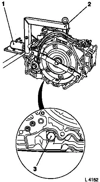
Attach fluid drain bolt (3) with new seal ring to transmission – tightening torque 40 Nm / 29.5 lbf. ft.

Remove transmission assembly from KM-113-2 (1) with KM-694-A (2).

Remove transmission from KM-694-A.

Install transmission – see operation "Transmission, Remove and Install (AF 20)".

Charge transmission fluid.

  Inspect

Check and correct level of transmission fluid – see operation "Transmission Fluid Level, Check and Correct (AF 13-II/AF 17/AF 20/AF 22)".

Object Number: 2416850  Size: DEFAULT


Related Literature Units
-
-
-
-
-
-

Multi-disc Brake B1, Remove and Install (AF 20) > < Fluid Pump, Disassemble and Assemble (AF 17)