|
Transmission, Remove and Install (AF 20)
Note: The drive unit
must be aligned to the front axle body using KM-6173 and KM-6001-A
in order to ensure correct alignment of the drive unit after
releasing the fastening bolt for the right and left engine damping
blocks. The attachment of KM-6173 and KM-6001-A is described in the
following.
 Remove Remove
If present: Remove lower engine cover – see operation
"Lower Engine Cover, Remove and Install" in group "A".
Remove front exhaust pipe, catalytic converter and centre
muffler.
 Install
|
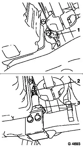
Attach KM-6173 (3) to front axle body – screw up support
bearing (2) until pins are seated flush in mount (1) on cylinder
block.
|
|
|
|
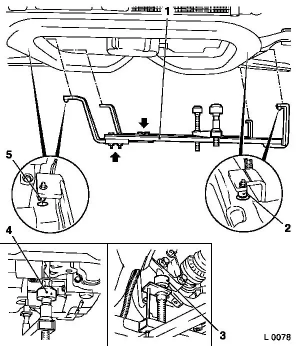
Release fastening bolts (arrows) for adjustment rails on
KM-6001-A (1).
Insert KM-6001-A as illustrated – pins (2) and (5) must
sit in guide holes of front axle body.
Tighten fastening bolts for adjusting rails.
Screw up front support bearing (4) and rear support bearing (3)
up to contact at guide pins of front engine damping block and rear
engine damping block bracket – guide pins must sit free of
play in support bearings.
|
Remove
Remove front axle body – see operation "Front Axle Body,
Remove and Install" in group "E". The Tools KM-6173 and KM-6001-A
remain on the front axle body and must not be moved.
|
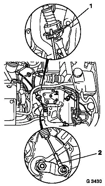
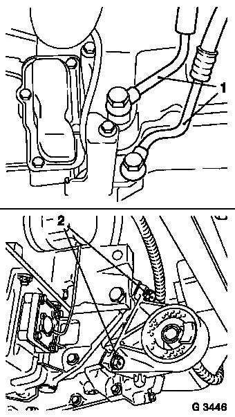
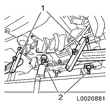
Press off selector actuation cable (2) from actuator lever.
Lever out retaining clamp (1) with screwdriver and unclip
selector actuation cable from counterholder.
Remove fluid filler pipe – see operation "Fluid Filler
Pipe and/or Gasket, Replace (AF 20)".
|
|
|
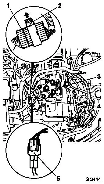
Disconnect wiring harness plug (1) of selector lever position
switch – at the same time release slide lock (2) in direction
of arrow.
Disconnect wiring harness plug of transmission wiring harness
– at the same time release slide lock in direction of arrow.
Remove transmission wiring harness from bracket (4).
Disconnect wiring harness plug of fluid temperature pickup
(5).
Remove fastening bolts for selector lever actuation cable
counterholder (3) with transmission wiring harness bracket from
transmission. Remove selector lever actuation cable counterholder
and transmission wiring harness bracket.
|
|
|
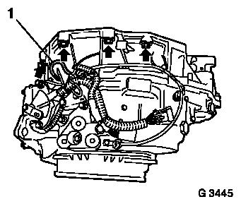
Detach transmission bleeding hose (1) from transmission.
Remove upper fastening bolts (arrows) for transmission (4
bolts).
Remove air filter housing with air intake hose – see
illustration "Air Flow Guide" in group "J".
|
|
|
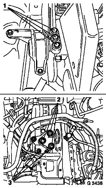
Remove fastening bolts (1) of right engine damping block.
Remove fastening bolts (2) of left engine damping block from
engine damping block main bracket.
Remove fastening bolts (3) of left engine damping block main
bracket.
Remove left and right axle shafts from transmission – see
operation "Axle Shafts, Remove and Install" in group "E".
|
|
For X 20 DTL engine: Remove coolant pipe from transmission.
|
Remove fluid cooler lines (1) from side cover and transmission
– place pan underneath and close off apertures. Note
installation sequence of fluid cooler lines.
Remove fastening bolts for front engine damping block (2) from
transmission. Remove front engine damping block.
Lower engine with transmission approx. 5 cm on MKM-883-1 –
ensure that coolant hoses and wiring harnesses are not
stretched.
|
|
For X 20 DTL engine: Remove starter – see operation
"Starter, Remove and Install" in group "J".
For X 20 XEV engine: Remove cap.
|
Remove fastening bolts (x 3 or x 6) for converter from drive
disc.
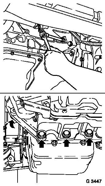
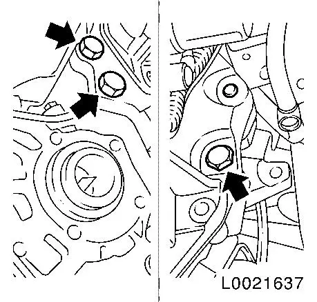
Remove lower fastening bolts (arrows) from transmission and
fluid sump.
Caution
Only remove fastening bolts for engine to lower part of
transmission once transmission holder DT-47648 is attached.
|
|
Install
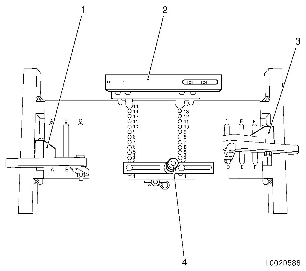
|
|
Set transmission mount DT-47648 on
KM-904 and preinstall as shown in illustration:
|
Part
|
Position on base plate
|
Name
|
|
DT-47648-2
(4)
|
2
|
Converter housing support
|
|
DT-47648-3
(2)
|
14
|
Transmission housing support
|
|
DT-47648-5 left
(1)
|
A
|
Transmission support with swivel arm, rear
|
|
DT-47648-5, right
(3)
|
F
|
Transmission support with swivel arm, front
|
|
|
Caution
Obey manufacturer's instructions for transmission mount
DT-47648.
Attach transmission mount DT-47648 to transmission
Note: Loosen all bolt
connections on the swivel arms and supports down to the base plate
before positioning. Turn the supports as far down as possible using
the spindles.
Position transmission mount DT-47648 with supports under
transmission
Tighten the bolt connections of the supports
Attach swivel arm (1) and (2) to transmission
Tighten the bolt connections on the swivel arm from the
transmission to the base plate
Note: Align the
swivel arms to minimize the leverage forces.
|
|
Remove
|
Install lower engine and transmission fastening bolts (arrows).
Press off transmission from engine and carefully drain – note
converter. Ensure that wiring harnesses and installation parts are
not damaged.
If necessary: Detach transmission from DT-47648.
Caution
Do not damage attaching parts when laying transmission down.
When replacing transmission: Drain fluid radiator to the extent
possible. Blow fluid radiator with low-pressure compressed air.
Blow fluid cooling lines on connections in both directions with
low-pressure compressed air.
|
|
Install
Attach transmission to DT-47648.
Caution
Follow manufacturer's instructions for DT-47648.
|
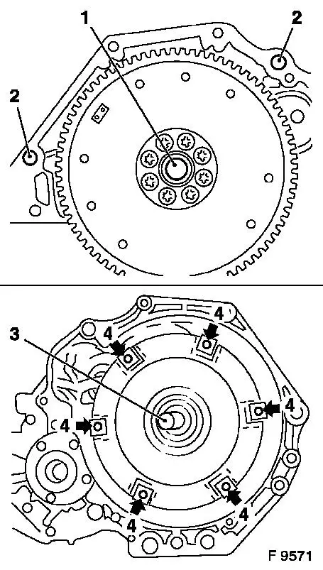
Prior to installing transmission: Coat centring seat (1) for
converter in crankshaft with grease.
When replacing transmission ensure that both guide drifts (2)
sit in engine flange.
Recut thread (4) of converter bolts in converter.
 Inspect
Check centring journal (3) for converter for frictional rust,
clean if necessary and lightly coat with assembly grease.
|
|
 Measure
|
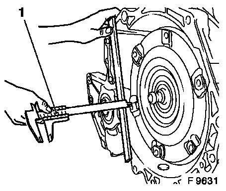
Measure distance between converter contact thread and
transmission housing contact surface with caliper gauge (1).
Distance Measuring Device AF 20: approx 13 mm.
|
|
Install
Raise transmission with hydraulic jack and DT-47648 and align.
Mount transmission evenly on engine – ensure correct seating.
Attach transmission to cylinder block – tightening torque 60
Nm / 44 lbf. ft. Detach DT-47648 from transmission.
Install transmission on fluid sump – tightening torque 40
Nm / 30 lbf. ft.
Attach converter to drive disc. Insert fastening bolts with
locking compound – first tighten all fastening bolts
uniformly to 20 Nm / 15 lbf. ft. Then tighten fastening bolts to 45
Nm / 33 lbf. ft. + 30°.
For X 20 XEV engine: Insert cap.
For X 20 DTL engine: Install starter – see operation
"Starter, Remove and Install" in group "J".
Install front engine damping block on transmission –
tightening torque 60 Nm / 44 lbf. ft.
Install axle shaft on right and left in transmission – see
operation "Axle Shaft, Remove and Install" in group "E".
Move engine with transmission on MKM-883-1 into original
position.
Install fluid cooler lines with new seal rings on transmission
and side cover – note installation sequence –
tightening torque 25 Nm / 18 lbf. ft.
Install front axle body – see operation "Front Axle Body,
Remove and Install" in group "E".
Caution
When installing the front axle body, ensure that support
bearings of KM-6001-A are correctly seated in the guide pins of the
front engine damping block and in the rear engine damping block
bracket. Pins of KM-6173 must sit in the cylinder block mount. If
necessary: Correct installation position of engine and transmission
using KM-883-1.
Do not yet install front exhaust pipe, catalytic converter,
centre muffler, battery carrier and battery.
Install
Install right engine damping block on right engine damping block
bracket – tightening torque 55 Nm / 41 lbf. ft.
Install air filter housing with air intake hose – see
illustration "Air Flow Guide" in group "J".
Install left engine damping block main bracket on transmission
(3 fastening bolts) – tightening torque 65 Nm / 48 lbf.
ft.
Install left engine damping block on left engine damping block
main bracket – tightening torque 55 Nm / 41 lbf. ft. Note
different bolt lengths.
Install upper transmission fastening bolts (4 bolts) on engine
– tightening torque 60 Nm / 44 lbf. ft.
Install fluid filler tube – see operation "Fluid Filler
Tube and/or Seal, Replace (AF 20/AF 22)".
Connect transmission bleeding hose to transmission.
Install selector actuation cable counterholder with transmission
wiring harness bracket on transmission – tightening torque 20
Nm / 15 lbf. ft.
Install selector actuation cable.
Connect wiring harness plug of fluid temperature pickup. Connect
and lock wiring harness plug of transmission wiring harness.
Connect and lock wiring harness plug of selector lever position
switch.
For X 20 DTL engine: Install coolant pipe on transmission
– tightening torque 20 Nm / 15 lbf. ft.
Remove Engine Mount KM-6001-A and Engine Support MKM-6173.
Install front exhaust pipe, catalytic
converter and centre muffler with new gaskets and fastening
nuts.
|
|
Engine (thread)
|
Tightening torque
|
|
Front exhaust pipe to exhaust manifold.
|
Y 20 DTL,
X 20 XEV, X 20 DTL, (M8)
|
20 Nm / 15 lbf. ft.
|
|
Centre muffler to rear muffler
|
Y 20 DTL, X 20 XEV, X 20 DTL (M8x1)
|
12 Nm / 9 lbf. ft.
|
If present: Install lower engine cover – see operation
"Lower Engine Cover, Remove and Install" in group "A".
Inspect
Check level of transmission fluid and correct if necessary
– see operation "Transmission Fluid Level, Check and Correct
(AF 13-II/AF 17/AF 20/AF 22)".
|
