|
Pressure Line from Clutch Master Cylinder to
Clutch Housing, Replace (RHD)
 Remove Remove
Charge brake fluid reservoir to "MAX" and close off with dummy
plug.
Remove battery.
Remove battery support.
|
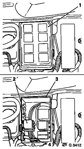
For vehicles with diesel engine: Remove relay holder cover (1)
from relay holder. Unclip relay (2) and fuse frame (4) with wiring
harness from relay holder (3) and set aside – note cable
routing.
Detach relay holder (3) and set aside.
|
|
|
Remove multiplug (1) and multiplug (2) from relay holder
bracket.
Remove relay holder bracket (3) (3 fastening nuts).
|
|
|
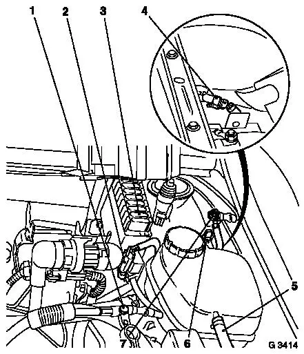
Detach coolant hose (5) from coolant compensation tank.
Remove retaining clamp (6) for coolant compensation tank, remove
coolant compensation tank. Disconnect wiring harness plug (4) from
underside of coolant compensation tank. Set aside coolant
compensation tank.
Remove steering wiring harness ground cable (7) from body.
Detach steering wiring harness plug (2).
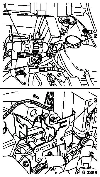
Remove cover from positive distribution. Detach fuse (3). Unclip
fuse frame from retainer.
Remove fastening bolt (1) and detach positive cable from
positive terminal.
|
|
|
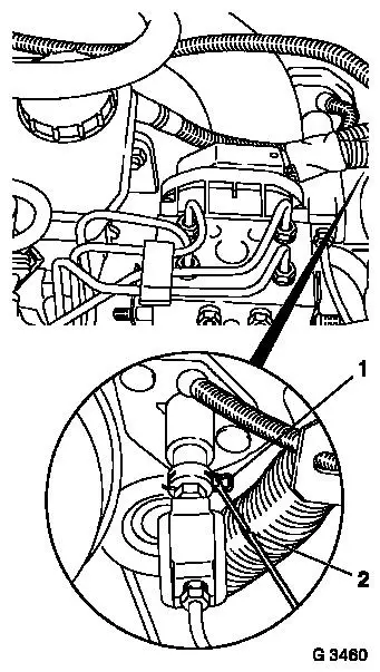
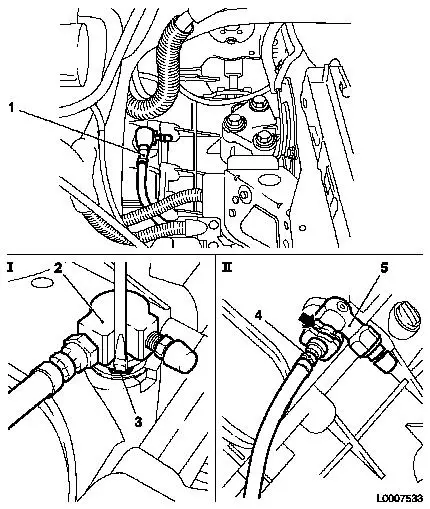
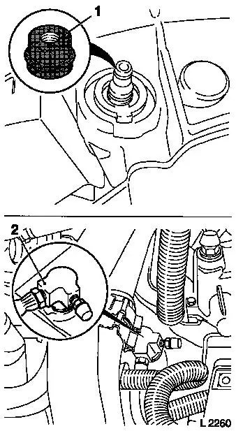
Release and remove retaining clamp (1) on clutch master cylinder
connector with screwdriver (2).
Detach clutch actuation pressure line from clutch master
cylinder connector.
Unclip clutch actuation pressure line from engine damping
block.
|
|
Remove
|
Detach pressure line (1) from central release.
I up to MY 2002: Remove pressure line with connector (2) from
central release pressure line on the transmission housing. Release
retaining clip (3) at connector with screwdriver and detach.
Remove clutch actuation pressure line with connector.
Remove clutch actuation pressure line from pressure hose
connector.
II as of MY 2002: Detach pressure line (4) from connector (5)
for central release pressure line on the transmission housing
– to do this, release retaining clip (arrow) at the connector
with screwdriver.
|
|
Caution
|
Pay attention to seating and state of O-ring (1) at pressure
line for central release. O-ring must not remain in connector.
 Install
Install clutch actuation pressure line on connector.
Insert clutch actuation pressure line with connector in engine
compartment.
Slightly bend retaining clip together and insert into
connector.
Attach pressure line (2) to central release on the clutch
housing.
|
|
Up to MY 2002: Connect pressure line with connector to central
release pressure line on clutch housing – clamp must audibly
engage.
As of MY 2002: Connect pressure line to connector for central
release pressure line on clutch housing – clamp must audibly
engage.
Clip clutch actuation pressure line on right engine damping
block.
Slightly bend retaining clamp together and insert in clutch
master cylinder connector. Press pressure line in clutch master
cylinder – engages audibly.
Install
Route steering wiring harness and make electrical connection
– tightening torque for ground connection 15 Nm / 11 lbf.
ft.
Install positive cable on battery positive terminal –
tightening torque 12.5 Nm / 9 lbf. ft.
Install relay holder bracket with new fastening nuts –
tightening torque 20 Nm / 15 lbf. ft.
Install multiplug (2 bolts) on relay holder bracket.
Connect relay holder to relay holder bracket.
For vehicles with diesel engine: Insert wiring harness with
relay and fuse frame in relay holder. Install relay holder cover on
relay holder.
Connect wiring harness plug to underside of coolant compensation
tank. Place coolant compensation tank in bracket and fasten with
clamp. Install coolant hose on coolant compensation tank. Charge
cooling system – see operation "Cooling System, Charge and
Bleed" in group "J".
Bleed hydraulic clutch actuation - see operation "Hydraulic
Clutch Actuation, Bleed (F13/F13+/F17/F17+/F18/F23/F35)".
Install battery support – tightening torque 15 Nm / 11
lbf. ft.
Install battery.
|
