|
Selector Lever Assembly, Remove and Install
(Adjustable Steering Column Assembly)
 Remove Remove
|
Remove steering wheel – see operation "Steering Wheel,
Remove and Install (Vehicles with Airbag)".
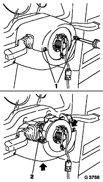
Remove boss from lever-adjustment. Pull out steering column to
stop and lock. Detach fastening bolts (1) from the upper part of
the signal switch panelling and detach the upper part of the signal
switch panelling from the lower part of the signal switch
panelling.
Detach fastening bolts (2 and arrow) from under part of signal
switch panelling. remove lower part of signal switch panelling.
Vehicles with airbag: Remove contact unit – see operation
"Contact Unit, Remove and Install" in group "C".
Unclip turn signal- and wiper switch from bracket.
|
|
|
Remove steering and ignition lock cylinder – see operation
"Steering and Ignition Lock Cylinder, Remove and Install" in group
"N".
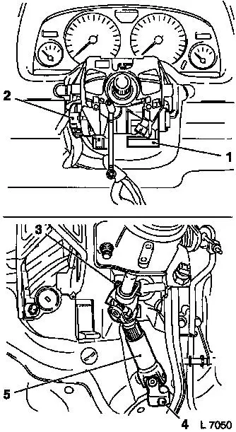
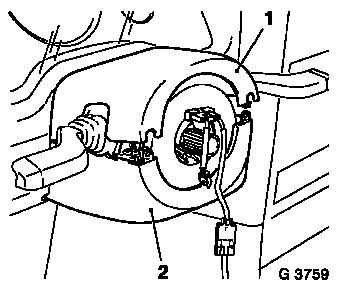
Remove immobiliser (1) control unit – see operation
"Immobiliser Control Unit, Remove and Install" in group "J".
Pull off contact part (2) for steering and ignition lock
downward from steering and ignition lock housing.
Remove footwell panelling and air distribution duct on driver's
side.
Remove upper (3) and lower (4) clamp bolt from intermediate
shaft (5). Push intermediate shaft together slightly and
remove.
Vehicles with ESP: Disconnect wiring harness plug from steering
angle sensor. Detach steering angle sensor from steering shaft
– see operation "Steering Angle Sensor, Remove and Install
(Vehicles with ESP)" in group "H".
|
|
|
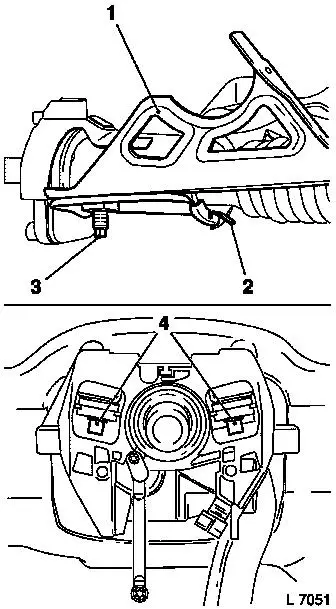
Loosen clamp bolt (3) on steering column assembly bracket (1)
until detent (2) releases the lower bearing sleeve of steering
column assembly – ensure that the detent is not bent.
Remove fastening bolts (4) for steering column assembly from
crossmember.
Remove steering column assembly. Ensure that attaching parts and
wiring harness are not damaged.
Note: When replacing
the steering column assembly in vehicles with ESP, the steering
angle sensor adapter for the steering shaft must be
transferred.
|
|
|
Caution
For vehicles up to MY '99, note TI-C-4, M-23 without fail before
installing the steering column assembly in order to avoid damaging
the lower steering column bearing.
 Install
Insert steering column-assembly in bracket (1) and reattach on
crossmember using fastening bolts – tightening torque 22 Nm /
16 lbf. ft.
Tighten clamp bolt (3) on steering column bracket – ensure
that the detent (2) is correctly positioned in front of the lower
bearing sleeve for the steering column assembly – tightening
torque 22 Nm / 16 lbf. ft.
Vehicles with ESP: Attach steering angle sensor to steering
shaft – see operation "Steering Angle Sensor, Remove and
Install (Vehicles with ESP)" in group "H".
|
|
|
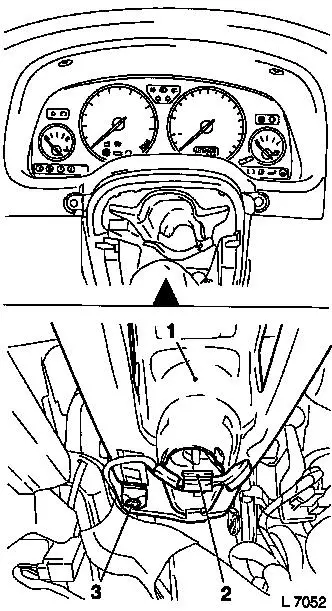
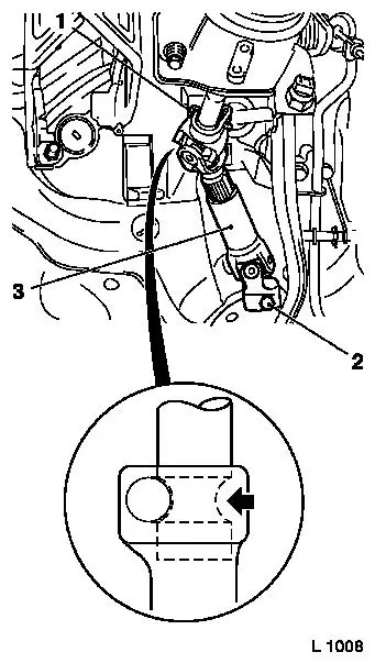
Push intermediate shaft (3) onto steering shaft and steering
gear shaft – ensure that the steering lock prevents the
steering shaft from rotating in the centre position and that the
wheels are in the straight-ahead position. Attach upper (1) and
lower (2) clamp bolt to intermediate shaft – clean thread and
insert clamp bolt with locking compound – tightening torque
22 Nm / 16 lbf. ft.
Caution
Before inserting clamp bolts, ensure that the groove (arrow) of
the steering shaft aligns with the bore of the intermediate
shaft.
Reinstall footwell panelling and air distribution duct on
driver's side.
Insert contact part for steering and ignition lock onto steering
and ignition lock housing from underneath.
|
|
Install
Reinstall immobiliser control unit – see operation
"Immobiliser Control Unit, Remove and Install" in group "J".
Install steering and ignition lock cylinder – see
operation "Lock Cylinder for Steering and Ignition Lock, Remove and
Install" in group "N".
Clip turn signal- and wiper switch onto bracket.
|
Vehicles with airbag: Install contact unit – see operation
"Contact Unit, Remove and Install" in group "C".
Pull out steering column to stop and lock. Reattach the lower
part of the signal switch panelling (2) using fastening bolts.
Attach boss to lever adjustment. Attach the upper part of the
signal switch panelling (1) to the lower part of the signal switch
panelling and attach fastening bolts.
Reinstall steering wheel – see operation "Steering Wheel,
Remove and Install (Vehicles with Airbag)". Fastening bolts -ensure
that the turn signal and wiper switch dust sleeves are seated
correctly.
Check straight ahead position, Adjust if necessary – see
operation "Straight Ahead Position Check/Adjust".
|
|
|
