B-Pillar, Exterior, Replace (Models L 35, L 48, L 69)
B-Pillar, Exterior, Replace (Models L 35, L 48, L
69)
Important: Note
specification for welded, brazed and riveted joints and body repair
with structural adhesive !
Important: Observe
SPP, PSO welding parameters for resistance spot welding! See TIS
Newsletter for equipment recommendations!
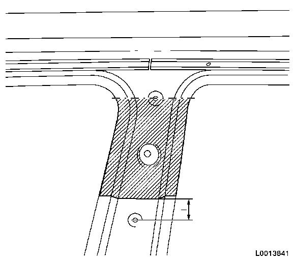
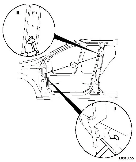
Remove
1.
Detach attaching parts
Important: When making the
parting cut on the exterior of the B-pillar, do not damage the
B-pillar reinforcement underneath it! Maximum submersion depth of
tool = thickness of material 0.8 mm
plus gap 1.5 mm
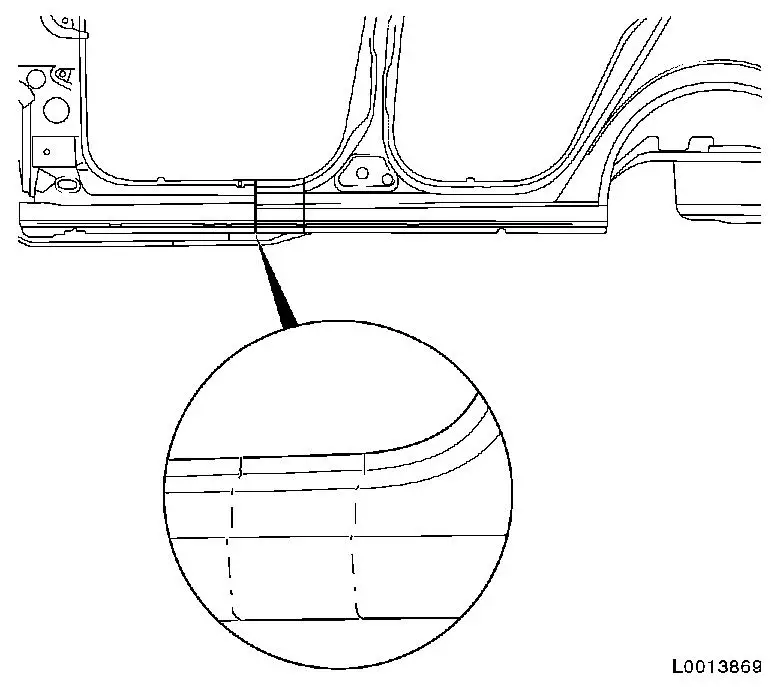
2.
Cut away exterior of B-pillar at the top
•
Mark parting cuts
–
I = approx. 30 mm Note: Parting cut at
the top is located centrally in the upper fixing bore of the
additional seal for the B-pillar!
3.
Drill away exterior of the B-pillar at the top
Important: Do not damage the
interior of the B-pillar underneath when making the parting cut in
the reinforcement of the B-pillar! Parting cut must be above the
mounting for the seat belt height adjustment on the interior of the
B-pillar!
4.
Cut interior reinforcement of the B-pillar
•
Mark parting line
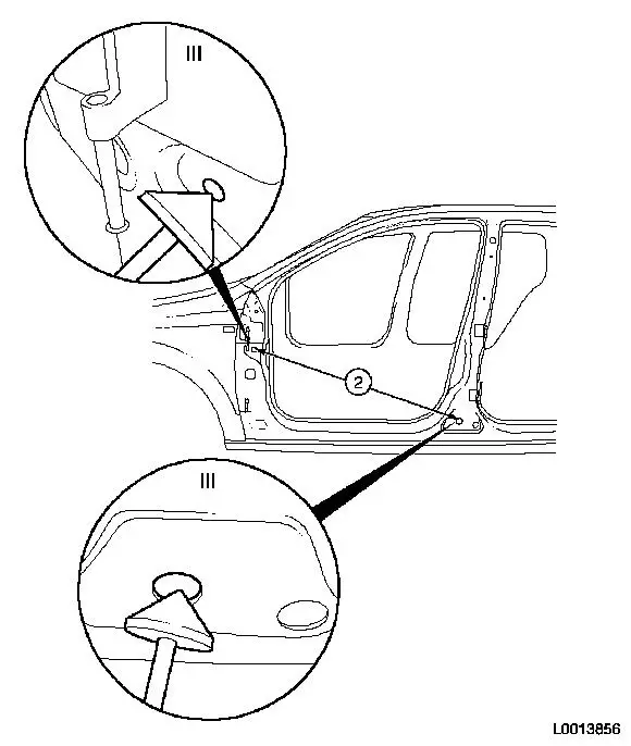
Important: Note size of new part!
When making the parting cuts for the exterior sill panelling, do
not damage the reinforcement for the B-pillar underneath it!
5.
Cut away front sill panelling
•
Mark parting cuts
6.
Drill away front sill panelling in area between the cutting
lines
Important: Note size of new part!
Do not damage the reinforcement on the interior of the sill
panelling with the parting cut!
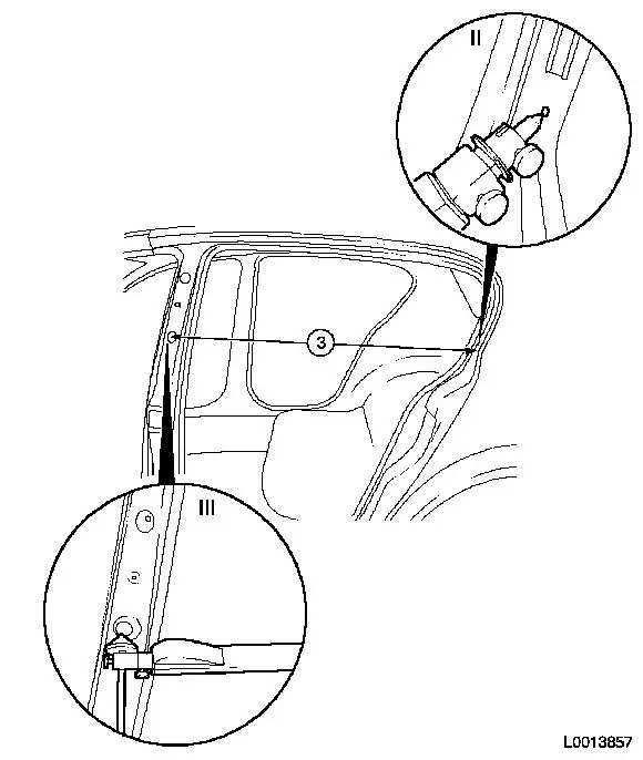
7.
Cut B-pillar away from the rear sill panelling
•
Mark parting line
–
I (model L 48) = approx. 430 mm
–
I (model L 35) = approx. 510 mm
8.
Drill away reinforcement of B-pillar at the front
•
Drill away 7x spot weld
Important: Do not drill into
reinforcement for sill panelling on the inside!
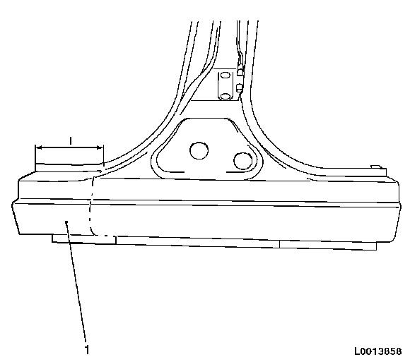
9.
Drill away lower B-pillar with interior reinforcement
10.
Drill B-pillar with reinforcement away from interior of
B-pillar Note: Remove drilling
and cutting swarf from cavities!
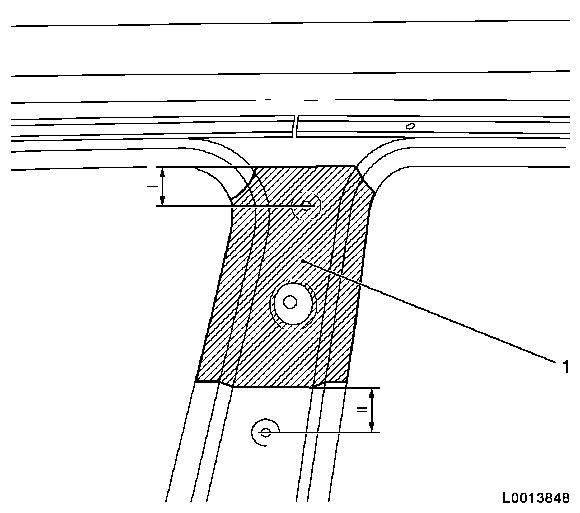
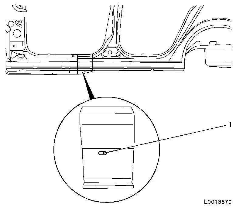
Install
Important: Note length of
connection area on the vehicle at the top of the B-pillar! Assembly
window (1) must be re-used! When making the parting cut on the
exterior of the B-pillar do not damage the reinforcement for the
B-pillar underneath it! Maximum submersion depth of tool =
Thickness of material 0.8 mm plus
gap 1.5 mm !
11.
Cut away exterior of B-pillar new part at the top
•
Mark parting cuts
12.
Drill away exterior of the B-pillar at the top
Important: Do not damage the
interior of the B-pillar underneath when making the parting cut!
Parting cut must be above the mounting for the seat belt height
adjustment on the interior of the B-pillar!
13.
Cut away reinforcement on inside of B-pillar new part
•
Mark parting line
Important: Do not damage original
spot welds in the drilling area! If there are overlaps, move hole
accordingly! Slots must be made for subsequent MIG-brazing!
14.
Prepare new part for lower B-pillar
•
Scribe 4 slots ( 6x20 mm ) Note: Arrow shows new
part in the installed position and direction of travel!
15.
Prepare new part for lower B-pillar
•
Scribe 3 slots ( 8x24 mm ) Note: Arrow shows new
part in the installed position and direction of travel!
Adjust exterior of B-pillar to fit Note: In addition,
observe body dimension chart!
•
1 = Diagonals A-/B-pillar ( 1136
mm )
–
III = 100 mm
18.
Adjust exterior of B-pillar to fit Note: In addition,
observe body dimension chart!
•
2 = Diagonals A-/B-pillar ( 1017
mm )
–
III = 100 mm
19.
Adjust exterior of B-pillar to fit Note: In addition,
observe body dimension chart!
•
3 = Opening of rear door frame - B-pillar to C-pillar ( 995 mm )
–
III = 30 mm
20.
Cut B-pillar to size at the top and at the rear sill
panelling Note: Joint on front
sill panelling is not cut to size until after the assembly window
has been adjusted to fit!
Important: Assembly window (1)
must be re-used!
21.
Remove B-pillar
22.
Cut B-pillar new part
•
Mark parting line
–
I = approx. 120 mm
23.
Adjust exterior of B-pillar to fit
•
See steps 17 to 19 Note: In addition,
observe body dimension chart!
24.
Remove B-pillar
25.
Make slots (1) at lower B-pillar reinforcement
•
Incorporate 3x ( 8x24 mm )
slot
Important: Pre-spot operation:
The number of spots is specified in the documentation from the
welding equipment manufacturer!
26.
Prepare sill panelling
Important: Pre-spot operation:
The number of spots is specified in the documentation from the
welding equipment manufacturer!
27.
Prepare new part, B-pillar
28.
Apply corrosion protection adhesive system 93 160 535 / 15 05
000 to interior of B-pillar
•
Leave at least 50 mm in the
connection area of the MIG-brazed seams free of adhesive!
•
Paint on surplus adhesive in the area of the lower sill
panelling as seam sealant and corrosion protection with a spatula
or flat brush
29.
Adjust exterior of B-pillar to fit
•
See steps 17 to 19 Note: In addition,
observe body dimension chart!
Important: Observe special
parameter program!
30.
Weld B-pillar Note: Do not weld
B-pillar top area (1) yet!
31.
MIG-braze top of B-pillar Note: Grind down
MIG-brazed seam in the joint area on the outside of the
B-pillar!
32.
MIG-braze the bottom of the B-pillar
33.
MIG-braze the bottom of the B-pillar Note: MIG-brazing the
slot (1) is undertaken subsequently with the front sill
panelling!
34.
MIG-braze the bottom of the B-pillar
35.
Fit the upper exterior B-pillar and cut to size
36.
Apply corrosion protection adhesive system 93 160 535 / 15 05
000 to interior reinforcement of B-pillar
•
Leave at least 20 mm in the
connection area of the MIG-brazed seams free of adhesive
•
Paint on surplus adhesive with a spatula or flat brush to fill
in the spot weld bores
Important: Observe special
parameter program!
37.
Weld upper outer B-pillar
38.
MIG-braze upper outer B-pillar
39.
Fit the front sill panelling and cut to size
40.
Prepare front sill panelling
•
Scribe slot ( 8x24 mm Note: mark slot (1)
corresponding to the position of the slot for the interior
reinforcement of the B-pillar (see step 35)!
41.
Make slot in front sill panelling
42.
Apply corrosion protection adhesive system 93 160 535 / 15 05
000 to interior reinforcement of B-pillar
•
Leave at least 20 mm in the
connection area of the MIG-brazed seams free of adhesive
Important: Observe special
parameter program!
43.
Weld front sill panelling
44.
MIG-braze front sill panelling
45.
MIG-braze front sill panelling at the bottom
46.
Grind MIG brazed seams
47.
Tighten bolt, steering crossmember 20
Nm
Important: The door hinges on the
delivered B-pillar are only tack welded!
48.
Adjust door hinges to fit and weld
49.
Seal body, weld and brazing seams Note: Observe corrosion
protection measures for seam seals.
50.
Apply underseal. Note: Observe corrosion
protection measures for PVC protection.
51.
Seal cavity Note: Observe
protective wax corrosion protection measures.