|
Replace brake servo (Z22YH)
 Remove Remove
| 1. |
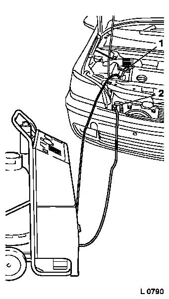
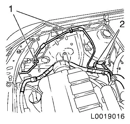
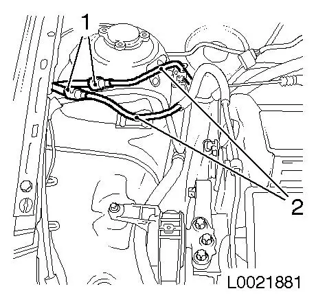
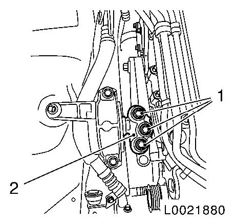
For vehicles with air conditioning: drain air conditioning
| • |
Connect service station
|
| • |
Blue hose to low pressure service connection (1) with small
diameter
|
| • |
Red hose to high pressure service connection (2) with large
diameter
Note: Comply with
operating instructions for service station
|
| • |
Determine quantity of compressor lubricant drawn out at the oil
separator of the service station
|
|
|
|
| 2. |
Remove air cleaner housing
|
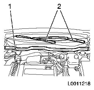
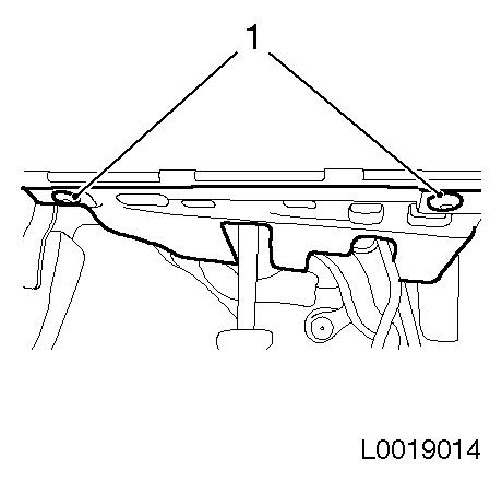
| 3. |
Remove seal of plenum cowl (1)
|
| 4. |
Remove windscreen wiper arms (2)
| • |
Remove 2x wiper arm from shaft
|
|
|
|
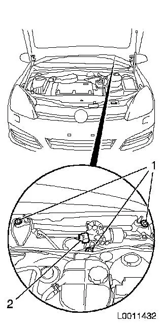
| 5. |
Remove windscreen wiper linkage with motor
| • |
Disconnect wiring harness plug (2)
|
|
|
|
| 6. |
Detach cover of brake fluid reservoir
|
| 7. |
Siphon out as much brake fluid as possible with siphon
bottle
|
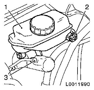
| 8. |
Unclip wiring harness from brake fluid reservoir (1)
|
| 9. |
Disconnect wiring harness plug (2) from brake fluid level
sensor
|
| 10. |
For vehicles with manual transmission: detach supply line for
clutch master cylinder from brake fluid reservoir
Note: Collect brake
fluid and seal apertures.
|
| 11. |
Detach brake line (3) from brake master cylinder
|
| 12. |
Detach brake master cylinder from brake servo
| • |
Unclip brake lines from bulkhead
|
|
|
|
| 13. |
Detach vacuum line from brake servo
|
| 14. |
Remove coolant line from expansion valve
|
|

|
| 15. |
Remove coolant line from wheel housing inner section
| • |
Unclip 2x from bracket (1)
|
|
|
|
| 16. |
Remove driver's side footwell panelling
|
|
|
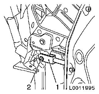
| 17. |
Detach piston rod for brake servo (1) from brake pedal
| • |
Remove pedal bolt from brake pedal (2)
| – |
Detach retaining spring
|
|
|
|
|
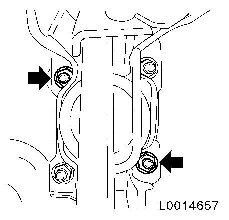
| 18. |
Detach brake servo from bulkhead
| • |
Unscrew 2x nut (arrows)
|
|
|
|
| 19. |
Remove 2x tank bleed line (2)
| • |
Open 2x fast closure (1)
|
| • |
Unclip 2x tank bleed line (2) and place to one side
|
|
|
|
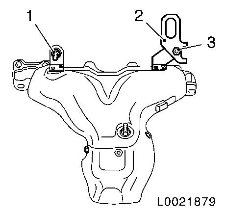
| 21. |
Detach rear engine transport shackle (2)
|
| 22. |
Unscrew exhaust manifold heat shield fastening bolt (1)
|
|
|
| 23. |
Detach front trim panel
|
| 25. |
Detach 2x brake line from bulkhead
|
|
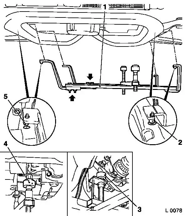
| 26. |
Attach KM-6001-A (1)
Note: Attaching KM-6001-A ensures perfect alignment of the
drive unit to front axle body
| • |
Undo 3x screw (arrows) for the adjusting rails
|
| • |
Insert KM-6001-A
| – |
Insert pins (2) and (5) in the guide holes for the front axle
body
|
|
| • |
Insert support bearings front (4) and rear (3)
| – |
Tighten support bearings to the stop on the guide pins
Note: Guide pins must
be seated without play in the support bearings
|
|
| • |
Tighten 3x screw for the adjusting rails
|
|
|
|
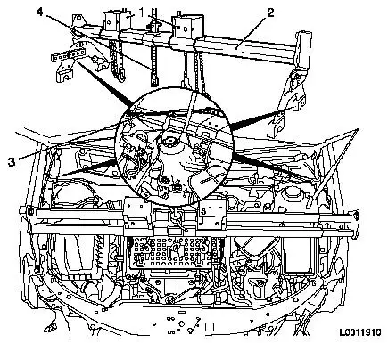
| 27. |
Attach MKM-883-1
|
Allocation list MKM-883-1:
|
|
Pos. no.:
|
Description
|
|
1
|
Jack
|
|
2
|
MKM-883-1
|
|
3
|
Safety hook
|
|
4
|
Safety spindle
|
|
| 28. |
Apply MKM-883-1
Note: 2nd person
required
Note: Secure wing
against tipping using safety hook (3) on engine bonnet hinge
|
|
| 29. |
Attach engine to engine bridge
|
| 30. |
Detach right engine damping block (2)
|
|
|
| 31. |
Lower engine
| • |
With hexagonal section on engine bridge
Note: Is removable up
to brake servo.
|
|
 Install
| 35. |
Attach engine damping block
|
| 36. |
Attach brake master cylinder to brake servo
|
| 37. |
Detach engine bridge MKM-883-1
Note: 2nd person
required
|
| 38. |
Tighten exhaust manifold heat shield fastening bolt 23 Nm
|
| 39. |
Attach engine transport shackle
|
| 40. |
Attach engine mount KM-6001-A
|
| 42. |
Attach brake servo to spray surface
|
| 43. |
Attach brake pedal bearing bolt
| • |
Attach retaining spring
|
|
| 44. |
Install lower footwell panelling
|
| 45. |
Attach 2x coolant line
| • |
Put in installation position
|
| • |
Clip on 2x upper coolant line
|
| • |
Attach 2x lower coolant line retainer
|
|
| 46. |
Attach coolant line to expansion valve
|
| 47. |
Attach wiring harness to brake fluid reservoir
| • |
Clip in 2x wiring harness
|
| • |
Connect wiring harness plug
|
|
| 48. |
Attach brake servo vacuum line
| • |
Close fast closure on inlet side
|
|
| 49. |
Attach brake master cylinder with brake fluid reservoir
|
| 50. |
Attach 2x brake line to bulkhead
|
| 51. |
2x brake line to brake master cylinder
| • |
Tighten 2x retaining bolt 14 Nm
|
|
| 53. |
Install 2x tank bleed line
|
| 54. |
Install windscreen wiper linkage with motor
| • |
Connect wiring harness plug
|
|
| 55. |
Attach plenum cowl
| • |
Attach hose, windscreen washing system
|
|
| 56. |
Install windscreen wiper arms
| • |
Plug 2x windscreen wiper arm on to shaft
Note: Note correct
installation position of the windscreen wiper arms!
|
|
| 57. |
Install seal of plenum cowl
|
| 59. |
Fill AC
| • |
Connect service station
|
| • |
Connect blue hose to low pressure service connection (1) with
small diameter
|
| • |
Connect red hose to high pressure service connection (2) with
large diameter
Note: Comply with
operating instructions for service station
|
| • |
Using the service station, add the quantity of new compressor
lubricant to the air conditioning which was drained out during
emptying
| – |
Fill air conditioning with refrigerant R 134a [155x77.5
L0790]]
|
|
|
| 60. |
Attach radiator grille
| • |
Attach 4x expanding rivet
|
|
| 62. |
Install front trim panel
|
|
