|
Repair engine using a short block
 Remove Remove
| 1. |
Detach transmission from engine
| • |
For vehicles with manual transmission 
|
| • |
For vehicles with automatic transmission
|
|
| 2. |
Vehicles with manual transmission: detach clutch
|
| 3. |
Vehicles with manual transmission: detach KM-6263
| • |
Turn rotating spindle back to initial position
|
|
| 4. |
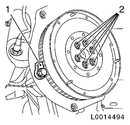
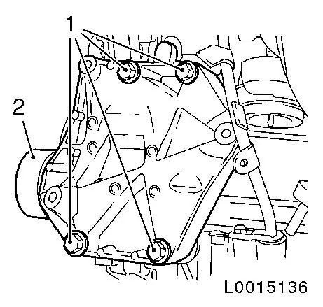
Vehicles with manual transmission: attach EN-46792 (1)
|
| 5. |
Vehicles with manual transmission: remove flywheel
|
|
|
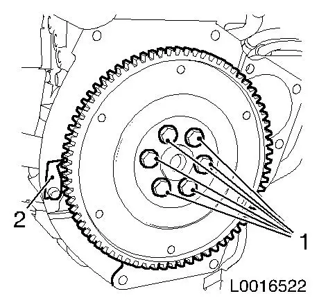
| 6. |
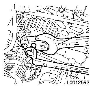
Vehicles with automatic transmission: attach EN-46792 (2)
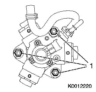
|
| 7. |
Vehicles with automatic transmission: remove drive disc
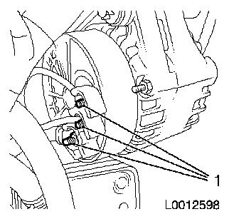
|
|
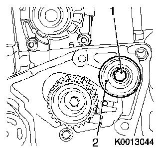
|
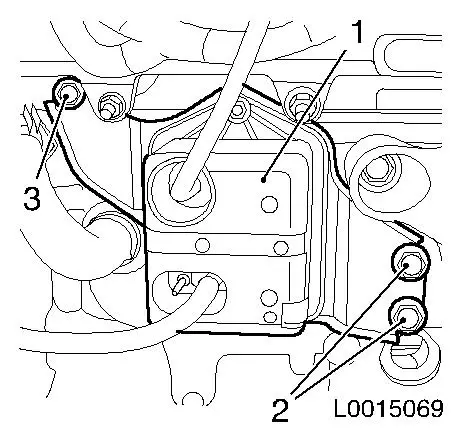
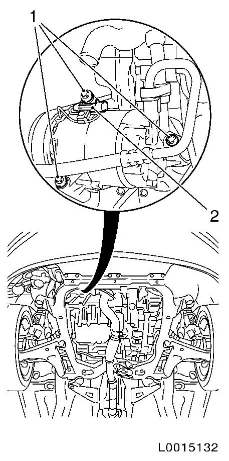
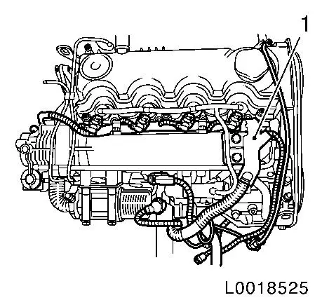
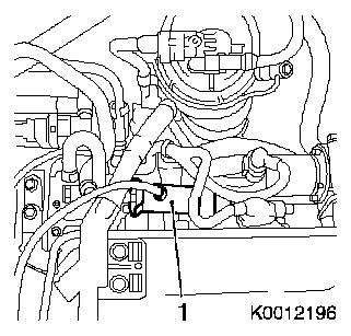
| 9. |
Detach vacuum reservoir (1) and retaining plate
Note: If present
|
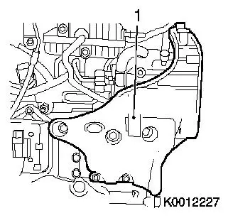
|
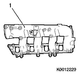
|
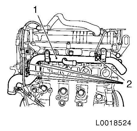
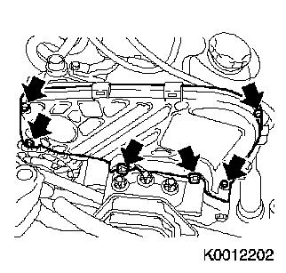
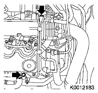
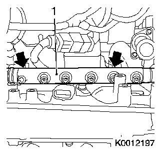
| 10. |
Detach EGR cooler (1)
| • |
Unscrew bolt, nut (arrows)
|
| • |
Detach EGR valve metal tube
|
|
|
|
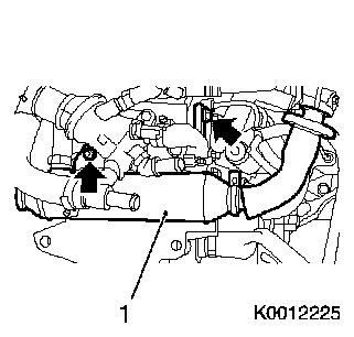
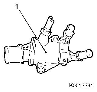
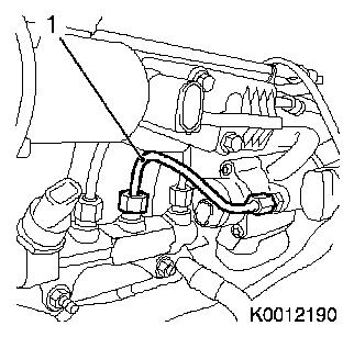
| 11. |
Remove thermostat housing (1)
| • |
Disconnect wiring harness connector.
|
|
|
|
| 12. |
Remove vacuum pump (1)
|
|
|
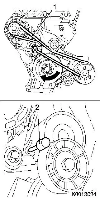
| 13. |
Remove ribbed V-belt (1)
| • |
Mark rotational direction of ribbed V-belt
|
| • |
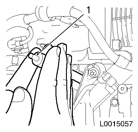
Tension ribbed V-belt tensioner in direction of arrow
|
|
|
|
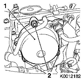
| 14. |
Remove compressor
| • |
Disconnect wiring harness plug (2)
|
|
|
|
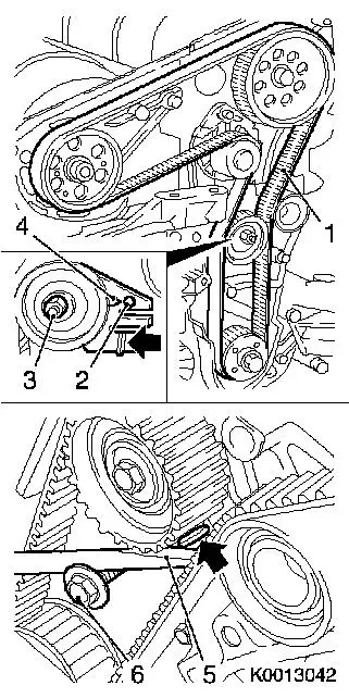
| 15. |
Detach compressor support from engine block
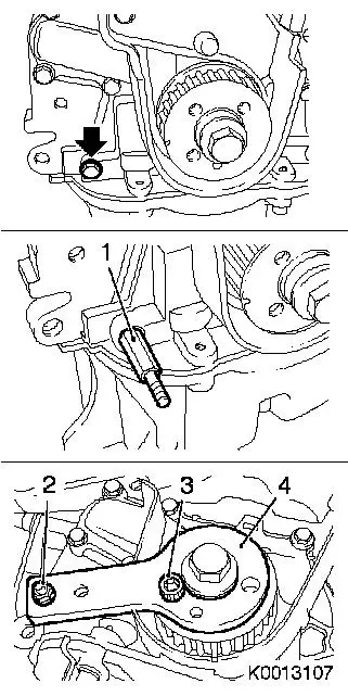
Note: Note guide
sleeves
| • |
Unscrew 4x bolts (1)
Note: Remove with
ribbed V-belt guide roller (2)
|
|
|
|
| 16. |
Detach 2x compressor wiring harness bracket
| • |
Unscrew 2x bolts
| – |
Set wiring harness aside
|
|
|
| 17. |
Remove coolant pipe assembly (1)
|
|
|
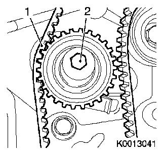
| 18. |
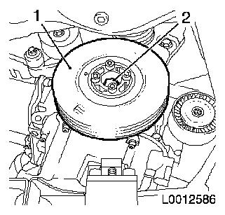
Remove torsional vibration damper (1)
| • |
Unscrew 4x bolts
Note: Counterhold
toothed belt drive gear at bolt (2)
|
|
|
|
| 19. |
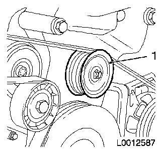
Remove upper ribbed V-belt guide roller (1)
|
|
|
| 20. |
Remove toothed belt cover
| • |
Unscrew 6x bolt (arrows)
|
| • |
4x unclip camshaft sensor wiring harness
|
|
|
|
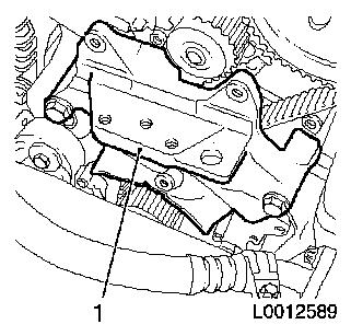
| 21. |
Remove engine damping block adapter (1)
| • |
Unscrew 5x bolts
Note: Note different
bolt lengths
|
|
|
|
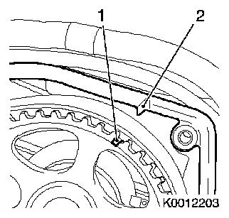
| 22. |
Set cylinder no. 1 to TDC of combustion stroke
| • |
The mark on the camshaft sprocket (1) must be aligned with the
mark on the camshaft housing cover (2)
|
|
|
|
| 23. |
Remove toothed belt (1)
Note: Mark direction of
rotation
| • |
Slacken the toothed belt tension roller
|
|
|
|
| 24. |
Remove toothed belt tightening roller
|
| 25. |
Remove toothed belt guide roller (2)
|
|
|
| 26. |
Detach vacuum line
| • |
Unscrew 2x bolts (arrows)
|
|
|
|
| 27. |
Detach witing harness (1) from engine
| • |
Detach wiring harness bracket from camshaft housing cover
|
| • |
Unclip 5x wiring harnesses
|
| • |
Disconnect 11x wiring harness plugs
| – |
Intake air temperature sensor
|
|
|
|
|
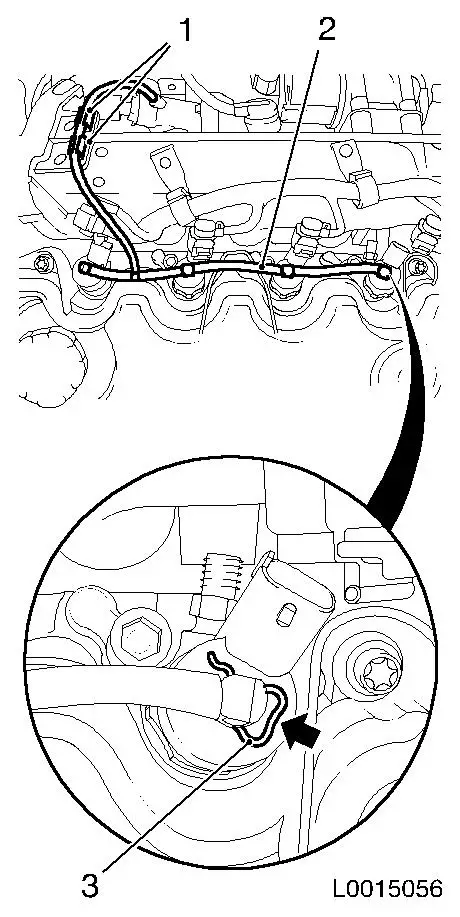
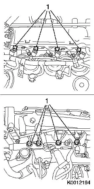
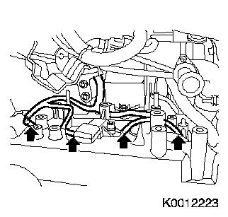
| 28. |
Detach 4x oil leak line (2) from injectors
Note: The oil leak line
must not be detached from the fuel return damping case. It if is
detached, it must be replaced.
| • |
Unclip 2x leak oil line (1)
|
| • |
Release 4x retaining clamp (3) from injector in direction of
arrow
Note: Seal 4x injectors
with suitable blanking plugs
|
|
|
|
| 29. |
Remove fuel return damping case (1) with oil leak line
Note: Open fuel
connections must be sealed with appropriate plugs
|
|
|
Important: After detaching the
high pressure lines, seal off injector and pressure chamber
openings with protective caps
1)
|
| 30. |
Detach accumulator high pressure line (1) to high pressure
pump
Important: When releasing the
retaining nut on the high pressure pump, counterhold with
open-ended wrench.
|
| • |
Unscrew 2x union nuts
Note: Fuel connections
that have been opened must be sealed with suitable plugs from the
kit (45 06 154).
|
|
|
|
| 31. |
Detach 4x high pressure line - accumulator to injector
Important: When releasing the
retaining nut, counterhold with open-ended wrench against the
injector.
|
| • |
Unscrew 8x union nut (1)
Note: Open fuel
connections must be sealed with suitable blanking plugs
|
|
|
|
| 32. |
Remove accumulator (1)
| • |
Unscrew 2x nut (arrows)
|
|
|
|
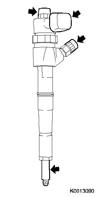
| 33. |
Remove 4x injector
Note: If the injectors
cannot be reached by hand, use EN-46786
together with KM-328-B . Fit plugs to
removed injectors (arrows).
|
|
|
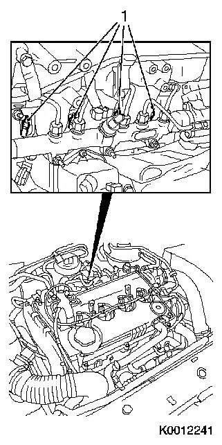
| 34. |
Detach wiring harness for sheathed glow plugs (arrows)
| • |
Disconnect 4x glow plug wiring harness plug
|
|
|
|
| 35. |
Remove 4x sheathed glow plug (1)
|
|
|
| 36. |
Release high-pressure pump gear
Note: Use a second
person
| • |
Counterhold with KM-6347 (1) in
combination with KM-956-1 (2)
|
|
|
|
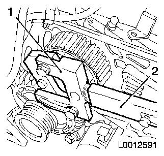
| 37. |
Detach high-pressure pump gear
| • |
Pull off high-pressure pump drive gear
| – |
Counterhold with open-ended wrench (2)
|
|
|
|
|
| 38. |
Remove high pressure pump
|
|
|
| 39. |
Detach 3x alternator wiring harnesses
|
|
|
| 41. |
Detach high-pressure pump bracket (1)
| • |
Detach coolant pipe bracket from high-pressure pump bracket
|
| • |
Unscrew 6x bolts
Note: Note different
bolt lengths
|
|
|
|
| 42. |
Remove intake manifold (1)
|
|
|
| 43. |
Detach alternator bracket
| • |
Unscrew 2x bolts
Note: Note different
bolt lengths
|
|
| 44. |
Detach cylinder head cover vent hose
|
| 45. |
Detach crankshaft housing vent hose
|
| 46. |
Detach charge air pipe bracket
|
| 47. |
Fit engine transport shackle
|
| 48. |
Hitch engine up to workshop crane.
|
| 49. |
Detach engine from KM-412
|
| 50. |
Detach KM-412-36-1 and KM-412-36-2 from engine block
|
| 51. |
Unhitch engine from workshop crane.
|
| 52. |
Detach engine transport shackle
|
 Install
| 53. |
Attach engine transportation shackle to engine short block
|
| 54. |
Hitch engine short block up to workshop crane
|
| 55. |
Attach KM-412-36-1 an KM-412-36-2 to engine block
|
| 56. |
Attach engine short block to KM-412
|
| 57. |
Unhitch engine short block from workshop crane.
|
Important: According to the
engine preparers' regulations all particles of dust and liquids
must be cleaned off every attaching part that is to be
reassembled.
|
| 58. |
Cleaning work on attaching parts
|
| 59. |
Detach engine transport shackle
|
| 60. |
Attach charge air pipe bracket
|
| 61. |
Attach crankshaft housing vent hose
|
| 62. |
Attach cylinder head cover vent hose
|
| 63. |
Attach alternator bracket
| • |
Tighten 2x bolts
Note: Note different
bolt lengths
|
|
| 64. |
Install intake manifold
| • |
Tighten 9x new nut 25 Nm
|
|
| 65. |
Attach high-pressure pump bracket
| • |
Tighten 6x bolt 25 Nm
Note: Note different
bolt lengths
|
| • |
Attach coolant pipe bracket to high-pressure pump bracket
|
|
| 66. |
Attach alternator
| • |
Tighten lower bolt 70 Nm
|
|
| 67. |
Attach alternator wiring harness
| • |
Tighten 2x nut (M6) 5 Nm
|
|
| 68. |
Install high pressure pump
|
| 69. |
Fit high pressure pump wheel
|
| 70. |
Fasten high-pressure pump gear
| • |
Counterhold with KM-6347 in
conjunction with KM-956-1
|
|
| 71. |
Tighten 4x sheathed glow plugs to 8
Nm
|
| 72. |
Attach wiring harness of sheathed glow plugs
| • |
Connect 4x wiring harness plug, sheathed glow plug
|
|
| 73. |
Cleaning work
| • |
Use EN-47632 (1) to clean the
injector seats. Insert EN-47632 with
coarse fleece in the injector shaft and clean the injector seat by
turning. Finish by cleaning with the fine fleece.
|
|
|
|
| 76. |
Install 4x new high-pressure line, accumulator to injector
| • |
Tighten 4x union nut (M14) 23 Nm
|
Important: Pressure lines must
not be installed more than once. When fastening the retaining nut
counterhold against the injector with an open-ended wrench.
|
| • |
Tighten 4x union nut (M12) 23 Nm
|
|
| 77. |
Attach new high pressure line - accumulator to high pressure
pump
| • |
Tighten union nut (M14) 23 Nm
|
Important: Pressure lines must
not be installed more than once. When fastening the union nut to
the high-pressure pump, counterhold against it with an open-ended
wrench.
|
| • |
Tighten union nut (M12) 23 Nm
|
|
| 78. |
Install fuel return damping case with oil leak line
| • |
Tighten 2x bolts
| – |
Attach wiring harness bracket to fuel return damping case
|
|
|
| 79. |
Attach 4x oil leak line to injectors
| • |
Clip 4x oil leak line to injector
|
|
| 80. |
Attach wiring harness to engine
| • |
Clip in 5x wiring harnesses
|
| • |
Connect 11x wiring harness plug
| – |
Intake air temperature sensor
|
|
| • |
Clip in 2x leak oil line
|
| • |
Attach wiring harness bracket to camshaft housing cover
|
|
| 83. |
Install toothed belt guide roller
| • |
Tighten bolt 50 Nm
Note: Use screw locking
compound (red)
|
|
| 85. |
Fit toothed belt tightening roll
Note: Insert tension
roller in guide
| • |
Use screw locking compound (red)
|
|
| 86. |
Install toothed belt
Note: Observe direction
of rotation
Important: Tightened end (1) must
be taut
|
| • |
Position toothed belt
|
|
| 87. |
Tension the toothed belt
| • |
Tension the toothed belt
Note: Push adjusting
lever in direction of arrow with a screwdriver (5) until pointer
(4) of toothed belt tension roller aligns with mark (2)
|
| • |
Tighten bolt, toothed belt tension roller (3) 25 Nm
|
|
|
|
| 88. |
Check crankshaft setting with EN-46788
| • |
Unscrew oil pump bolt (arrow)
|
| • |
Tighten stud bolt (1) EN-46788
|
| • |
Attach positioning disk (4) EN-46788
|
| • |
Detach positioning disk EN-46788
|
|
|
|
| 89. |
Timing, Check
| • |
Turn crankshaft 720° in the
direction of rotation of the engine
|
| • |
Check camshaft position
| – |
The mark on the camshaft sprocket must align with the mark on
the cylinder head cover.
|
|
|
| 90. |
Check crankshaft setting with EN-46788
Note: If EN-46788 cannot be fitted, repeat the toothed belt
positioning procedure
| • |
Attach positioning disk EN-46788
|
| • |
Remove positioning disk and stud bolt EN-46788
|
| • |
Tighten oil pump bolt 9 Nm
|
|
| 91. |
Install engine damping block adapter
Note: Note different
bolt lengths
| • |
Tighten 3x bolt (M10) 50 Nm
|
| • |
Tighten 2x bolt (M8) 25 Nm
|
|
| 92. |
Install toothed belt cover
| • |
Tighten 4x bolt (M6) 9 Nm
|
| • |
Tighten 2x bolt (M8) 25 Nm
|
| • |
4x clip in camshaft sensor wiring harness
|
|
| 93. |
Install upper ribbed V-belt guide roller
|
| 94. |
Install torsional vibration damper
Note: Observe correct
fitting position
| • |
Tighten 4x bolt 25 Nm
Note: Counterhold
toothed belt drive gear at bolt
|
|
| 95. |
Install coolant pipe assembly
|
| 96. |
Attach 2x compressor wiring harness bracket
|
| 97. |
Attach compressor support to engine block
Note: Note guide
sleeves
|
| 98. |
Attach compressor to support
| • |
Fix wiring harness plug
|
|
| 99. |
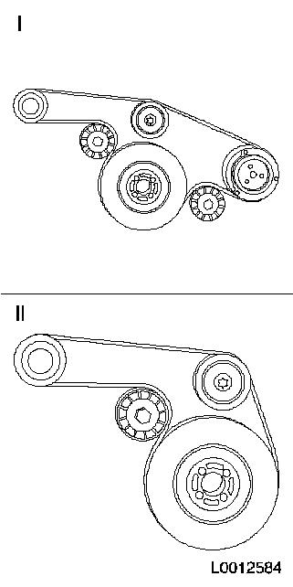
Insert ribbed V-belt
Note: Note direction of
travel
| • |
Position ribbed V-belt
| – |
I Route of ribbed V-belt with air conditioning
|
| – |
II Route of ribbed V-belt without air conditioning
|
|
|
|
|
| 100. |
Clean sealing surface
|
| 102. |
Clean sealing surface
|
| 103. |
Install thermostat housing
| • |
Fix wiring harness plug
|
|
| 104. |
Insstall EGR cooler
| • |
Attach EGR valve metal tube
|
|
| 105. |
Attach vacuum reservoir and retaining plate
|
| 108. |
Vehicles with automatic transmission: install drive disc
| • |
Tighten 6x new bolt 160 Nm
|
|
| 109. |
Vehicles with manual transmission: install flywheel
| • |
Tighten 6x new bolt 160 Nm
|
|
| 110. |
Vehicles with manual transmission: attach KM-6263
Important: Fasten KM-6263 but only to engine block, not to oil pan
|
| • |
Tighten 4x bolts
|
| • |
Insert clutch pin KM-6263-30 with
KM-6263-22
|
|
| 111. |
Vehicles with manual transmission: install clutch
|
| 112. |
Detach transmission from engine
| • |
Remove automatic transmission from engine
|
| • |
Remove manual transmission from engine
|
|
1 ) Protective caps are available from the Opel
parts catalogue under catalogue number 45 06 154 / part number:
9201697
|
