|
Camshaft Housing, Replace
Important: When
working on the fuel system it is essential to pay attention to
cleanliness as even the smallest dirt particles can lead to faults
in engine operation or in the fuel system. Open fuel connections
must be sealed with appropriate plugs from the Opel Parts Catalogue
(catalogue number: 45 06 154 / part number: 9201697). Sealing plugs
are only intended to be used once.
 Remove Remove
| 2. |
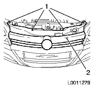
Detach radiator grille (2)
| • |
Detach 4x body-bound rivets (1)
|
| • |
Unclip from front panelling
|
|
|
|
| 3. |
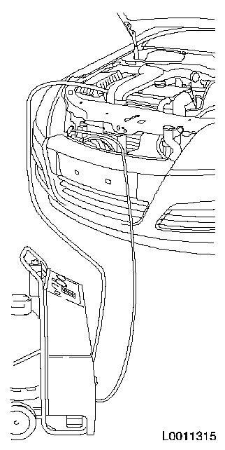
Empty climate control system
| • |
Connect service station
|
| • |
Blue hose to low-pressure service connection with small
diameter
|
| • |
Red hose to high-pressure service connection with large
diameter
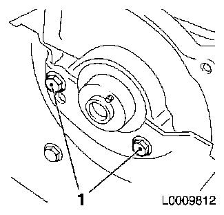
Note: Read Service
Station operating instructions carefully
|
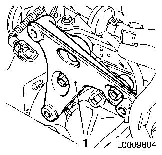
| • |
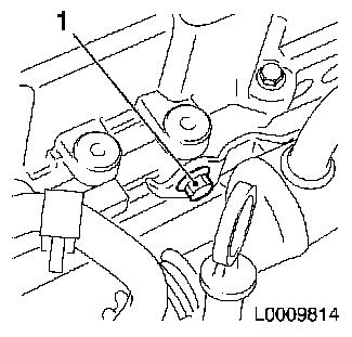
Determine quantity of condenser extracted at the oil separator
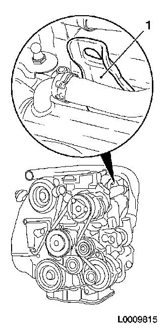
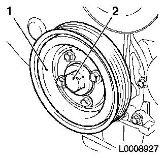
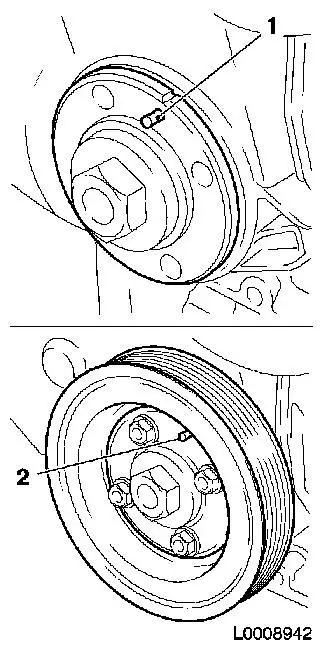
of the Service Station
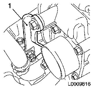
|
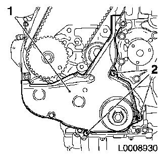
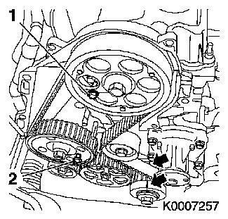
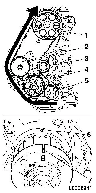
|
|
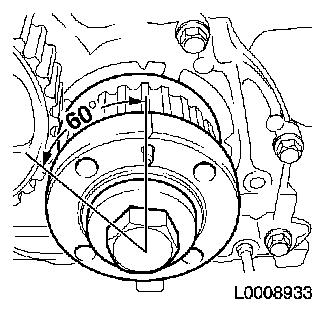
|
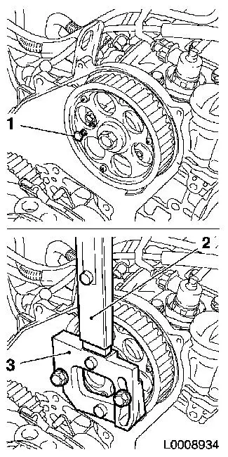
| 4. |
Disconnect battery
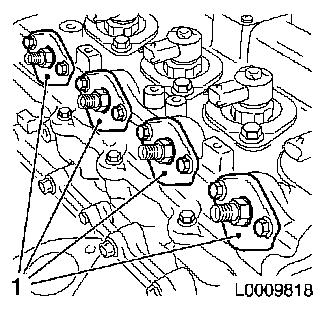
| • |
Detach earth connection from earth terminal
|
|
| 5. |
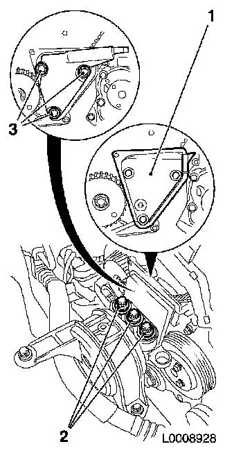
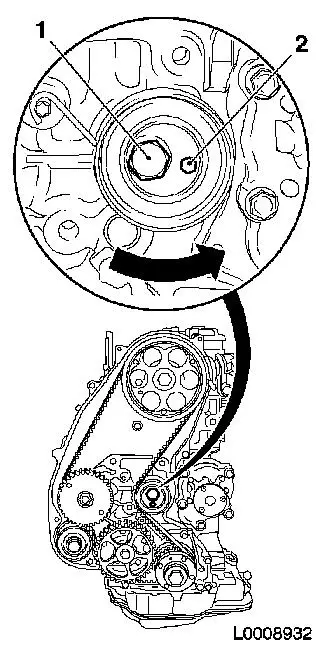
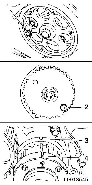
Raise vehicle by its full height
|
| 6. |
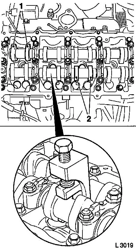
Detach the lower engine cover and right engine splash guard
|
| 7. |
Place collecting basin underneath.
|
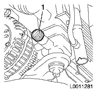
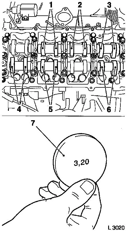
| 8. |
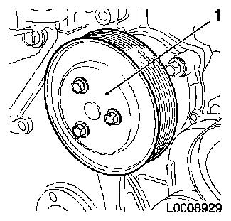
Drain coolant
| • |
Open drain bolt on radiator (1)
|
|
|
|
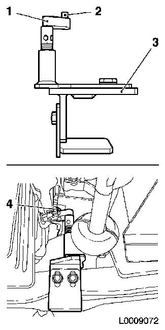
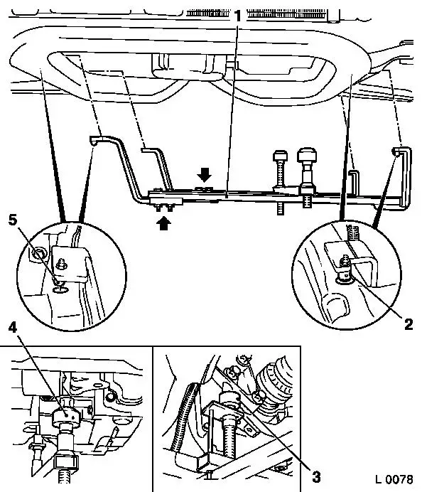
| 9. |
Insert KM-6173 (3)
| • |
Align support bearing (1)
|
| • |
Raise support bearing until journal (2) sits flush in mount
(4)
|
|
|
|
| 10. |
Attach KM-6001-A (1)
Note: Attaching
KM-6001-A guarantees perfect alignment of the drive unit with the
front axle body
| • |
Slacken 4x bolts (arrows) in adjusting rails
|
| • |
Insert KM-6001-A
| – |
Insert journals (2) and (5) in guide holes in front axle
body
|
|
| • |
Tighten 4x bolts in adjusting rails
|
| • |
Adjust support bearings, front (4) and rear (3)
| – |
Raise support bearings up to the stop on the guide journals
Note: The guide
journals must be seated free from play in the support bearings
|
|
|
|
|
| 11. |
Lower vehicle by its full height
|
| 12. |
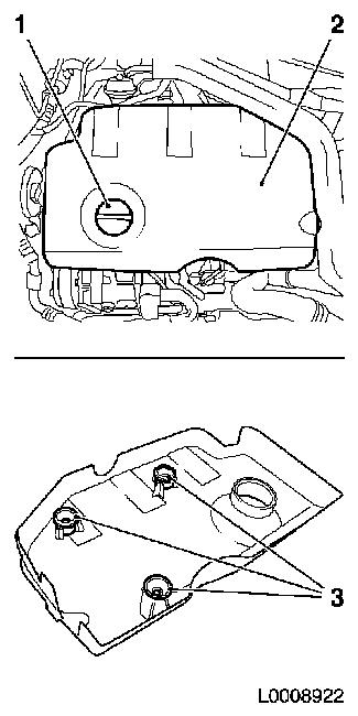
Remove engine cover (2)
| • |
Detach oil filler port closure cap (1)
|
| • |
Pull off engine cover
Note: Rubber retainers
(3) must remain on engine cover
|
| • |
Attach oil filler port closure cap
|
|
|
|
| 13. |
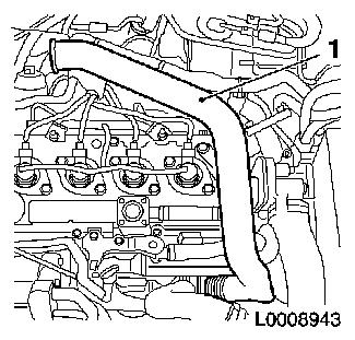
Remove air intake manifold (1)
|
|
|
| 14. |
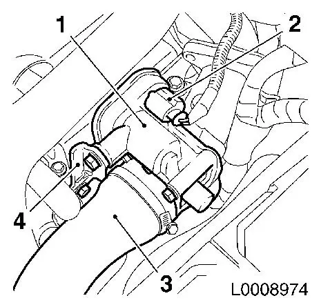
Remove throttle valve body (1)
| • |
Detach charge air hose (3)
|
| • |
Release bracket, throttle valve body (4)
| – |
Detach from throttle valve body
|
| – |
Release on camshaft housing
|
|
| • |
Disconnect wiring harness plug (2).
|
|
|
|
| 15. |
Remove charge air pipe (1)
|
|
|
| 16. |
Detach wiring harness for injectors
| • |
Disconnect 4x wiring harness plugs for injector (2)
|
| • |
Disconnect 4x wiring harness plug for glow plug (1) with KM-717
|
| • |
Push wiring harness to one side
|
|
|
|
| 17. |
Place collecting basin underneath.
|
Important: After detaching the
pressure lines, seal off injector and pressure chamber openings
with protective caps
1)
|
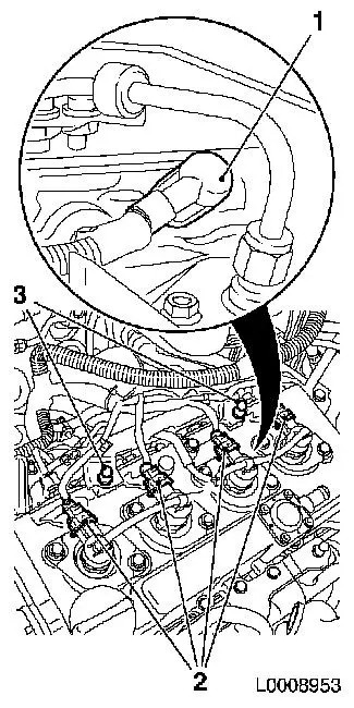
| 18. |
Remove high pressure lines (1), pressure chamber to
injectors
| • |
Unscrew 8x union nut with KM-812 or
KM-6098
|
| • |
Take out pressure lines
|
| • |
Seal 4x pressure chamber opening with protective cap
|
| • |
Seal 4x injector opening with protective cap
|
|
|
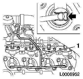
|
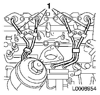
| 19. |
Detach fuel return line (1)
| • |
Detach 4x fuel return line from injector
| – |
Press 4x retaining clamps in direction of arrow
|
|
| • |
Detach fuel return line from pressure chamber
|
| • |
Unscrew 2x bolts
Note: Note different
bolt lengths
|
|
|
|
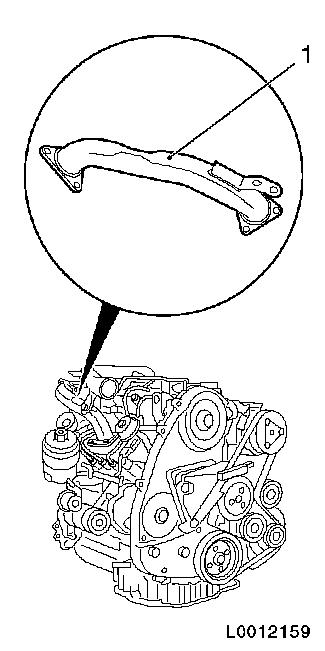
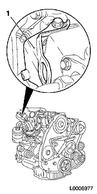
| 20. |
Remove rear right engine transport shackle (1)
|
|
|
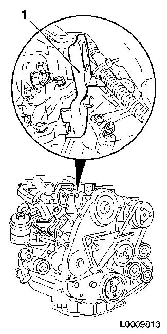
| 21. |
Remove rear left engine transport shackle (1)
|
|
|
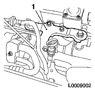
| 22. |
Remove bracket, oil dipstick guide tube (1)
| • |
Remove oil dipstick guide tube
|
| • |
Detach bracket, oil dipstick guide tube, from camshaft
housing
|
|
|
|
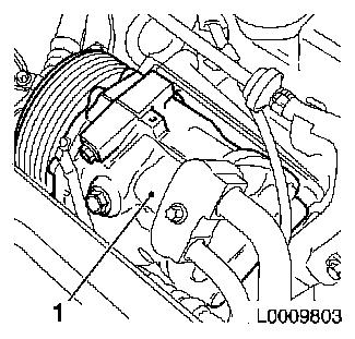
| 23. |
Remove compressor (1)
| • |
Detach refrigerant lines
|
| • |
Disconnect wiring harness connector.
|
| • |
Unscrew 3 bolts
Note: Note different
bolt lengths
|
|
|
|
| 24. |
Remove compressor bracket (1)
|
|
|
| 25. |
Detach cooler, exhaust gas recirculation (1) from camshaft
housing
|
|
|
| 26. |
Detach right front engine transport shackle (1)
|
|
|
| 27. |
Detach bracket, throttle valve body (1), from camshaft
housing
|
|
|
| 28. |
Remove 4x seals, connection for injectors (1)
|
|
|
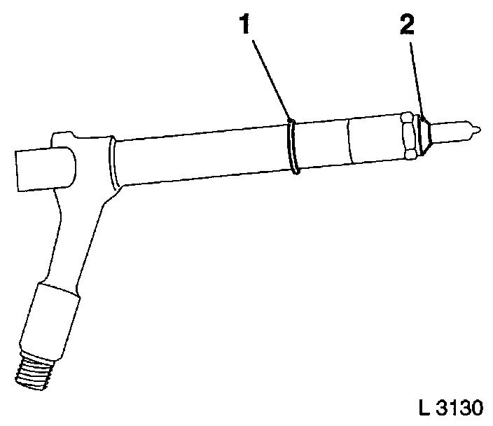
| 29. |
Remove 4x seal, injectors (1)
|
|
|
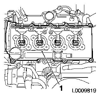
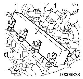
| 30. |
Remove camshaft housing cover (1)
| • |
Unscrew 11x bolts
Note: Note different
bolt lengths
|
|
|
|
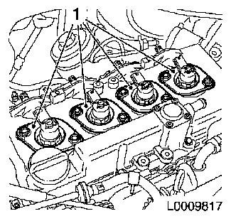
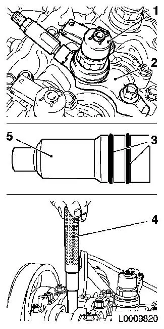
| 31. |
Remove 4x injector (1)
Note: Mark
injectors
| • |
Remove 4x bracket, injector (2)
| – |
Unscrew 4x bolts
Note: If a heat
protection sleeve (5) also has to be removed when removing an
injector, the gaskets (3) must be replaced and the heat protection
sleeve must be hammered into the cylinder head with KM-6357 (4)
|
|
|
|
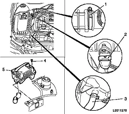
|
| 32. |
Remove air cleaner housing (5) with air intake hose
| • |
Detach wiring harness plug (2) from hot film mass air flow
meter
|
| • |
Detach air intake hose from air intake pipe
|
| • |
Detach air cleaner housing from wheel housing
|
| • |
Detach water drain hose (3) from air cleaner housing
|
|
|
|
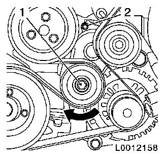
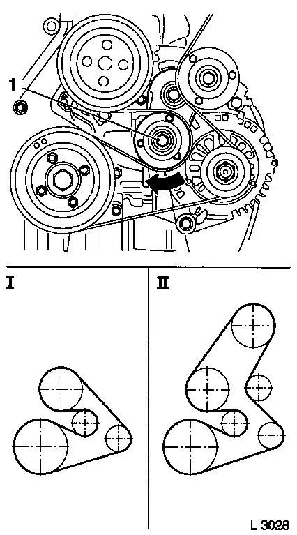
| 33. |
Remove ribbed V-belt
| • |
Mark direction of rotation
|
| • |
Apply tension to ribbed V-belt tensioner via bolt (1) in the
direction of the arrow
|
| • |
Fix ribbed V-belt tensioner to bore (2)
|
|
|
|
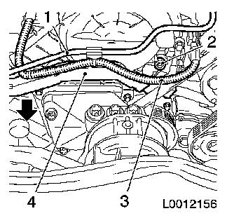
| 34. |
Detach wiring trough (4) from front toothed belt cover
(top)
| • |
Detach wiring harness (3)
| – |
Disconnect camshaft sensor wiring harness plug
|
|
| • |
Unclip wiring trough in direction of arrow
|
|
|
|
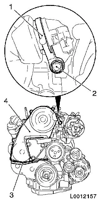
| 35. |
Detach front toothed belt cover (top) (4)
| • |
Unscrew 8x bolts
Note: Note different
bolt lengths
|
| • |
Remove camshaft sensor bracket (1)
|
|
|
|
| 36. |
Remove engine damping block support
| • |
Detach from engine damping block bracket
|
| • |
Detach from cylinder block
|
| • |
Remove engine damping block adapter (1)
|
|
|
|
| 37. |
Remove coolant pump drive gear (1)
|
|
|
| 38. |
Detach torsional vibration damper (1)
| • |
Unscrew 4x bolts
Note: Counterhold at
bolt (2)
|
|
|
|
| 39. |
Remove front toothed belt cover (lower) (1)
|
|
|
| 40. |
Move crankshaft in direction of engine rotation to "Cylinder
no.1 combustion stroke TDC"
Note: Marking on
toothed belt drive gear must align with projection on oil pump
cover (arrows)
| • |
Fix with TDC fixing bolt (M6) (1) camshaft drive gear
|
| • |
Fix with TDC fixing bolt (M8) (2) high pressure pump gear
|
|
|
|
| 41. |
Remove toothed belt
| • |
Mark direction of rotation
|
| • |
Slacken the toothed belt tension roller
|
| • |
Apply preliminary tension to toothed belt tension roller with
hexagon (2) in direction of arrow
|
| • |
Fix toothed belt tension roller in pre-tensioned position
|
|
|
|
| 42. |
Turn crankshaft 60° against the direction of engine
rotation
|
|
|
| 43. |
Remove camshaft sprocket
| • |
Remove TDC fixing bolt (1)
|
| • |
Unscrew bolt
Note: Counterhold with
KM-6347 (2) in conjunction with KM-956-1 (3)
|
|
|
|
| 44. |
Detach rear toothed belt cover from camshaft housing
|
|
|
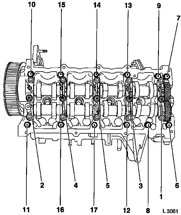
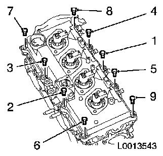
| 45. |
Remove camshaft housing
| • |
Unscrew 17x bolt
| – |
Slacken in the order shown (1 - 17) 1/2 turn and then
remove
|
|
|
|
|
 Install
| 47. |
Clean sealing surfaces.
|
| 48. |
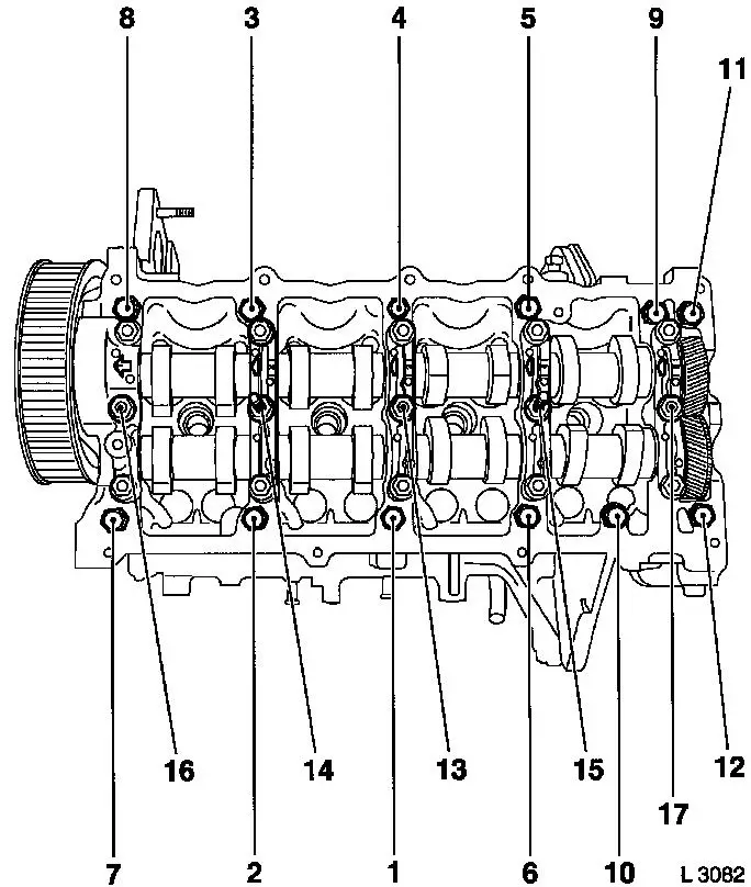
Install camshaft housing
| • |
Attach to cylinder head and tighten in the order shown
(1-17)
| – |
Tighten 12x bolt (M8) 21.6 Nm
|
| – |
Tighten 5x bolt (M10) 26.5 Nm
|
|
|
|
|
| 49. |
Attach rear toothed belt cover to camshaft housing
|
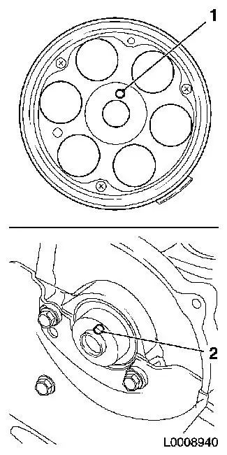
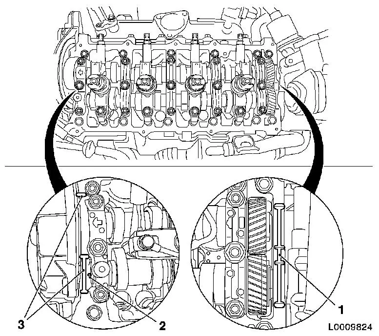
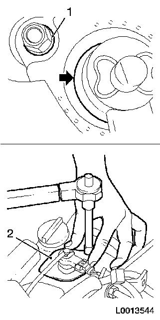
| 50. |
Install camshaft sprocket
Note: Camshaft journal
(2) must engage in the bore (1) in the camshaft sprocket
| • |
Tighten bolt 63.7 Nm
Note: Counterhold with
KM-6347 in conjunction with KM-956-1
|
| • |
Screw in TDC fixing bolt
|
|
|
|
| 51. |
Install toothed belt
Note: TDC fixing bolts
must be installed in the high pressure drive gear and camshaft
drive gear and markings (6) and (7) must align
| • |
Position toothed belt
| – |
Toothed belt must be tensioned in the direction of the arrow
from the toothed belt drive gear (5) via the oil pump drive gear
(4) and high pressure pump drive gear (2) to the camshaft sprocket
(1)
|
| – |
Observe direction of rotation
|
|
| • |
Slacken the toothed belt tension roller (3)
|
| • |
Remove 2x TDC fixing bolt
|
| • |
Turn crankshaft 60° against the direction of engine
rotation
|
| • |
Tighten toothed belt tension roller 38.2 Nm
|
|
|
|
| 52. |
Timing, Check
| • |
Turn crankshaft 6 revolutions in direction of engine rotation
to the adjustment position
|
| • |
The following factors must be present at the adjustment
position
Note: If one of these
factors is not present, the timing must be adjusted
| 1. |
TDC fixing bolt M6 (1) must be able to be inserted
in the camshaft drive gear |
| 2. |
TDC fixing bolt M8 (2) must be able to be inserted
in the high pressure pump drive gear |
| 3. |
Marking (4) on the toothed belt drive gear must
align with the marking (3) on the oil pump housing cover |
|
| • |
Remove 2x TDC fixing bolt
|
|
|
|
| 53. |
Turn the crankshaft until the cam pair (1) and (2) faces
upwards.
|
| 54. |
Check valve lash with feeler gauge
Note: Valve lash must
be checked at room temperature when the engine is cold.
| • |
Test values: Intake valve/exhaust valve (0.35 - 0.45 mm)
|
|
| 55. |
Adjust valve play
| • |
Turn the bucket tappet until the tappet groove faces
outwards
|
Important: Care should be taken
that the valves do not strike the piston head
|
| • |
Press down cup tappet with KM-6090
Note: Note different
tool designs for intake and exhaust valve
| – |
Marking - IN = intake side
|
| – |
Marking - EX = exhaust side
|
|
|
|
|
| 56. |
Example for determination of shim thickness:
|
1.
|
Thickness of installed shim
|
|
3.15 mm
|
|
2.
|
Measurement between cams and cup tappets
|
+
|
0.45 mm
|
|
|
|
=
|
3.60 mm
|
|
3.
|
Nominal valve play
|
-
|
0.40 mm
|
|
4.
|
Thickness of new shim
|
=
|
3.20 mm
|
|
| 57. |
Insert shim
| • |
Coat new shim (7) with engine oil and insert in cup tappet with
code facing down
|
|
| 58. |
Check and adjust remaining valves
| • |
Turn crankshaft 180° in the direction of rotation of the
engine
| – |
Check and adjust valve pair (6) and (2)
|
|
| • |
Turn crankshaft 180° in the direction of rotation of the
engine
| – |
Check and adjust valve pair (5) and (3)
|
|
| • |
Turn crankshaft 180° in the direction of rotation of the
engine
| – |
Check and adjust valve pair (4) and (1)
Note: Valve lash must
be checked again on all adjusted valves
|
|
|
|
|
| 59. |
Install front toothed belt cover (lower)
|
Important: Journal (1) of toothed
belt drive gear must engage in the bore (2) of the torsional
vibration damper
|
| 60. |
Install torsional vibration damper
| • |
Tighten 4x bolt 19.6 Nm
Note: Counterhold
against bolt, toothed belt drive gear
|
|
|
|
| 61. |
Install coolant pump drive gear
| • |
Tighten 3x bolt 12.3 Nm
|
|
| 62. |
Install engine damping block bracket
| • |
Insert engine damping block adapter
|
| • |
Attach engine damping block support to cylinder block
|
| • |
Engine damping block support to engine damping block
bracket
|
|
| 63. |
Install front toothed belt cover (top)
| • |
Tighten 8x bolt 9.8 Nm
Note: Note different
bolt lengths
|
| • |
Install camshaft sensor bracket
|
| • |
Attach vacuum line to toothed belt cover
|
|
| 64. |
Attach wiring trough to front toothed belt cover (top)
| • |
Attach wiring harness
| – |
Connect camshaft sensor wiring harness plug
|
|
|
| 65. |
Detach pressure chamber
| • |
Unscrew 2x bolts 1 - 1 1/2 turns
|
|
| 66. |
Replace injector gaskets
|
|
|
| 67. |
Install 4x injector
| • |
Install 4x brackets
| – |
Align injectors with EN-48560 (1)
|
|
|
|
|
| 68. |
Fasten 4x high pressure lines for pressure chamber to
injector
| • |
Fit 8x union nuts finger-tight
|
|
| 69. |
Fasten 4x injectors
| • |
Tighten 4x bolt in three stages
|
|
|
|
| 70. |
Fasten pressure chamber
|
| 71. |
Detach 4x high-pressure lines from pressure chamber to
injector
| • |
Seal off connections on pressure chamber with suitable sealing
plugs
|
| • |
Seal injector connections with protective caps
|
|
|
| 72. |
Apply sealing compound
Important: Oil return bore (2)
may not be covered with adhesive sealing compound
|
| • |
Apply adhesive sealing compound (white) to sealing surfaces (1)
and (3)
|
|
|
| 73. |
Install camshaft housing cover
| • |
Tighten 9x bolt in the stated order (1...9) 9.8 Nm
|
|
|
|
| 74. |
Install 4x new seal, injectors (2)
| • |
Align seal for injectors
Note: Sealing lip of
seal must be in full contact with the injector with no gaps
(arrow)
|
| • |
Coat 8x bolt head contact surface (1) with special grease
(white)
|
| • |
Tighten injector seal in 2 stages
Note: During the
tightening process, press injector seal against the camshaft
housing cover with your hand
| 1. |
Tighten 2x bolt 10
Nm |
| 2. |
Tighten 2x bolt 19
Nm |
|
|
|
|
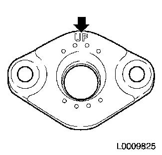
| 75. |
Install 4x new seal, connection for injectors
Note: Marking "UP" must
point upwards
|
|
|
| 76. |
Attach throttle valve body bracket to camshaft housing
|
| 77. |
Attach right front engine transport shackle
|
| 78. |
Attach cooler, exhaust gas recirculation to camshaft
housing
|
| 79. |
Install bracket, oil dipstick guide tube
| • |
Attach bracket, oil dipstick guide tube, to camshaft
housing
|
| • |
Attach dipstick guide tube
|
|
| 80. |
Install compressor bracket
|
| 81. |
Attach compressor
Note: Note different
bolt lengths
| • |
Tighten 3x bolt 24.5 Nm
|
|
| 82. |
Install rear left engine transport shackle
|
| 83. |
Install rear right engine transport shackle
|
| 84. |
Install fuel return line
Note: Note different
bolt lengths
| • |
Attach 4x fuel return line to injector
|
| • |
Attach fuel return line to accumulator
|
|
| 85. |
Install 4x high-pressure lines
| • |
Tighten 8x union nut with KM-812 or
KM-6098 25
Nm
Note: Tighten union
nuts first at injectors, then at pressure chamber
|
|
| 86. |
Attach wiring harness for injectors
| • |
Connect 4x wiring harness plugs, glow plug
|
| • |
Connect 4x injector wiring harness plug
|
|
| 88. |
Install throttle valve connecting piece
| • |
Fix wiring harness plug
|
| • |
Attach throttle valve body bracket to throttle valve body
|
| • |
Attach throttle valve body bracket to camshaft housing
|
|
| 89. |
Install air intake pipe.
|
| 90. |
Insert ribbed V-belt
Note: Note running
direction of ribbed V-belt
| • |
Position ribbed V-belt
| – |
I. Ribbed V-belt without air conditioning
|
| – |
II. Ribbed V-belt with air conditioning
|
|
| • |
Apply tension to ribbed V-belt tensioner via bolt (1) in the
direction of the arrow
|
| • |
Release ribbed V-belt tensioner
|
|
|
|
| 91. |
Raise vehicle by its full height
|
| 92. |
Remove engine mount KM-6173
|
| 93. |
Remove engine mount KM-6001-A
|
| 94. |
Install lower engine cover and right engine splash guard
|
| 95. |
Lower vehicle by its full height
|
| 96. |
Install air cleaner housing with air intake hose
| • |
Attach water drain hose to air cleaner housing
|
| • |
Attach air intake hose to air intake pipe
|
| • |
Connect wiring harness plug to air mass flow meter
|
|
| 97. |
Install engine cover
| • |
Detach oil filler port closure cap
|
| • |
Attach oil filler port closure cap
|
|
| 98. |
Cooling System, Charge and Bleed
|
| 99. |
Connect battery
| • |
Attach earth connection to earth terminal
|
|
| 100. |
Program volatile memories
|
| 101. |
Top up climate control system
| • |
Connect service station
|
| • |
Connect blue hose to low pressure service connection with small
diameter
|
| • |
Connect red hose to high pressure service connection with large
diameter
Note: Read Service
Station operating instructions carefully
|
| • |
Use the Service Station to insert the quantity of new
compressor lubricant into the climate control system that was
extracted when it was emptied.
| – |
Fill air conditioning system with R 134a refrigerant
|
|
|
|
|
| 102. |
Install radiator grille
| • |
Clip upwards into front panelling
|
| • |
Install 4x body-bound rivets
|
|
1 ) Protective caps are available from the Opel
parts catalogue under catalogue number 45 06 154 / part number:
9201697
|
