|
Camshaft Housing, Replace
Important: When
working on the fuel system maintaining cleanliness is essential, as
even the smallest of dirt particles may result in engine operating
faults or fuel system faults. Open fuel connections must be sealed
off with suitable sealing plugs from the Opel parts catalogue.
Sealing plugs are designed for single use only.
 Remove Remove
| 1. |
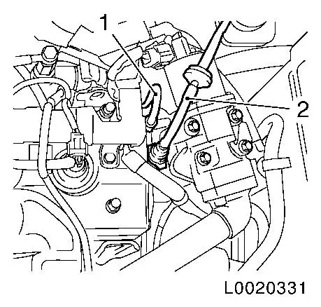
Remove air cleaner housing
|
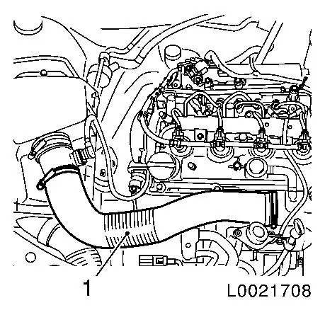
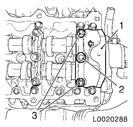
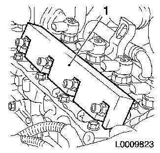
| 3. |
Remove air intake manifold (1)
|
|
|
| 4. |
Disconnect battery
| • |
Detach earth connection from earth terminal
|
|
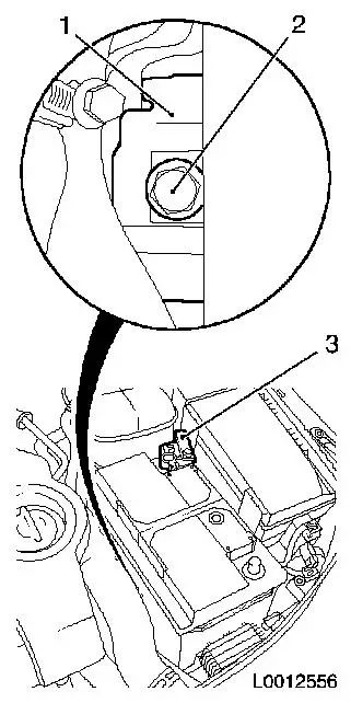
| 5. |
Remove battery
| • |
Detach positive terminal (3) from positive pole
|
|
|
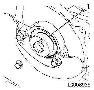
|
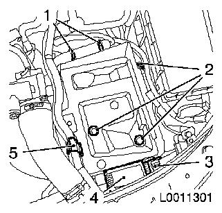
| 6. |
Remove battery support.
| • |
Unclip control unit of pre-heating system (4)
|
| • |
Unclip coolant hose bracket (5)
|
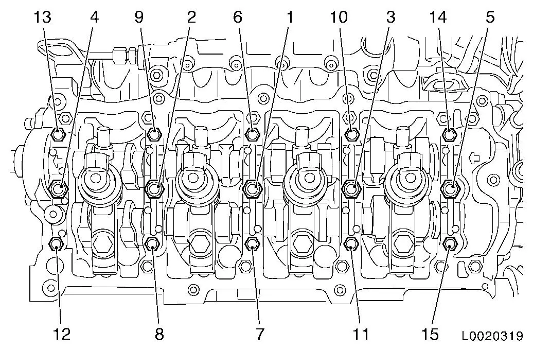
| • |
Detach wiring harness
| – |
Unclip 2x from battery support (1)
|
|
| • |
Unclip wiring harness plug (3)
|
|
|
|
| 7. |
Raise vehicle by half its height
|
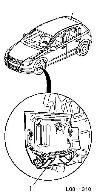
| 8. |
Detach wiring harness from engine control unit
| • |
Release and unplug wiring harness plug (1) from engine control
unit
|
| • |
Unclip wiring harness from bracket
|
| • |
Unclip 3x wiring harnesses from engine
|
|
|
|
| 9. |
Lower vehicle by half its height
|
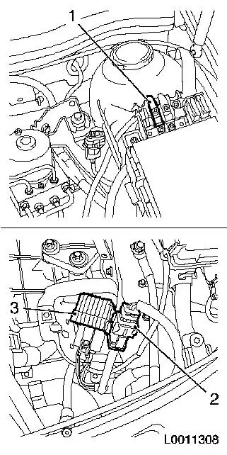
| 10. |
Disconnect upper engine timing wiring harness
| • |
Detach fuse carrier cover
|
| • |
Detach positive cable (1) from fuse carrier
Note: Mark installation
position
|
| • |
Release and unplug wiring harness plug (2)
|
| • |
Unclip wiring harness and expose
|
|
|
|
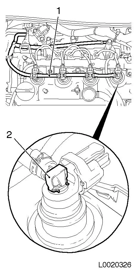
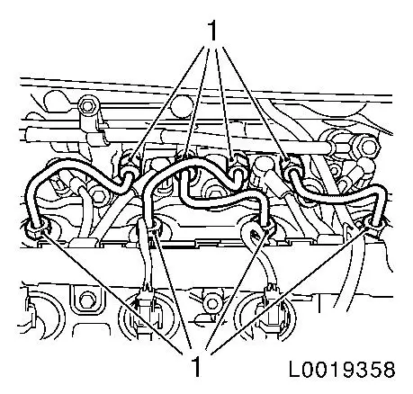
| 11. |
Detach fuel return line (1) from injector
| • |
4x from injector
| – |
Release retaining clamps (2)
|
|
| • |
Seal off line and connections with sealing caps
|
|
|
|
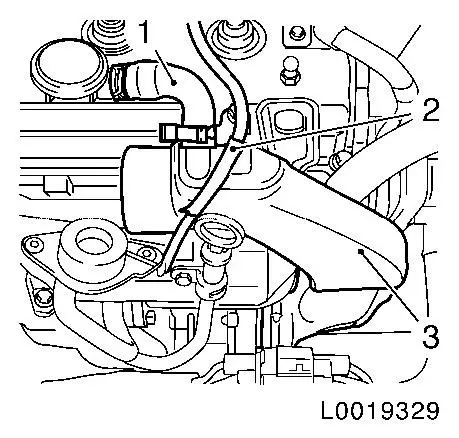
| 12. |
Detach charge air pipe (3) from camshaft housing cover
| • |
Detach camshaft vent hose (1) from charge air pipe
|
| • |
Unclip hose for wastegate unit of exhaust gas recirculation
cooler bypass valve (2)
|
|
|
|
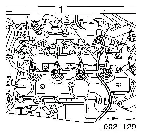
| 13. |
Detach vacuum hose (1) of wastegate unit for exhaust gas
recirculation cooler
|
|
|
| 14. |
Detach engine management wiring trough (1) from camshaft
housing cover
| • |
Unscrew 3 bolts (arrows)
|
|
|
|
| 15. |
Disconnect engine management wiring harness plugs
| • |
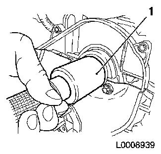
Disconnect 14x wiring harness plugs
| – |
4x sheathed glow plugs
Note: Release with
EN-48558 and pull off by hand
|
| – |
Coolant temperature sensor
|
|
| • |
Unclip 2x wiring harnesses
|
|
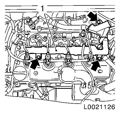
| 16. |
Remove 4x high-pressure lines
| • |
Unscrew 8x union nut (1)
|
| • |
Seal off connections on pressure chamber with suitable sealing
caps
|
|
|
|
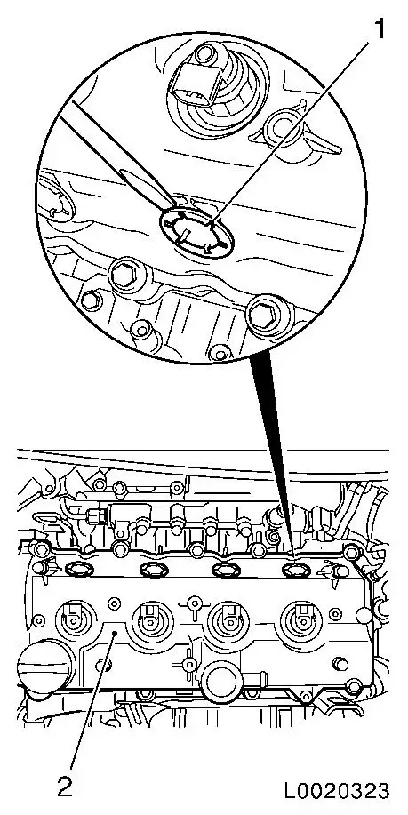
| 17. |
Remove camshaft housing cover (2)
| • |
Remove 4x injector seals (1)
|
| • |
Remove camshaft housing cover
|
| • |
Seal off connections on injector with EN-48559
|
|
|
|
| 18. |
Remove 4x injector (1)
|
|
|
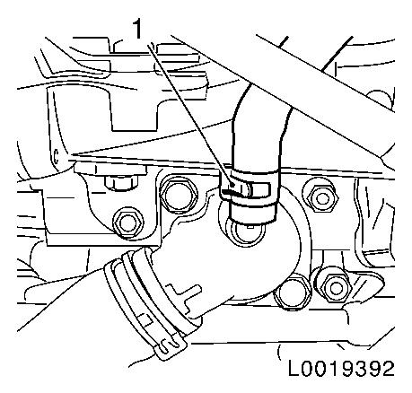
| 19. |
Detach coolant hose (1) from thermostat housing cover
|
|
|
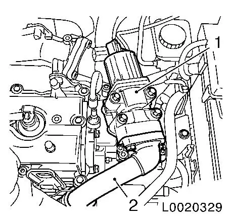
| 20. |
Remove exhaust gas recirculation valve (1)
| • |
Detach EGR cooler pipe (2)
|
|
|
|
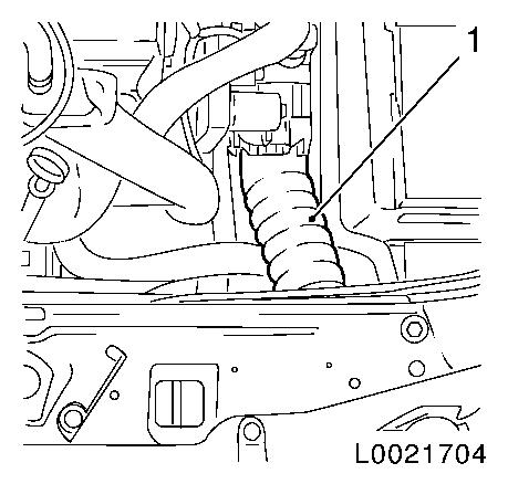
| 21. |
Detach charge air hose for throttle valve connection (1)
|
|
|
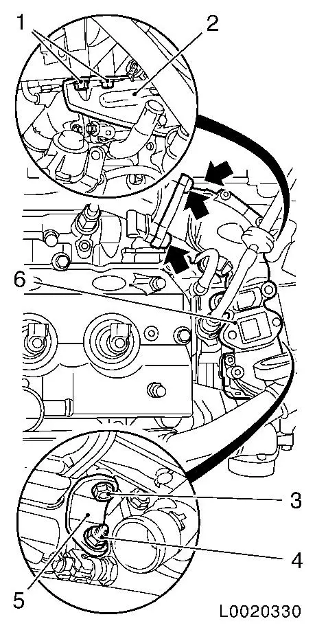
| 22. |
Detach intake pipe rear bracket (2) from intake pipe (6)
|
| 23. |
Remove intake pipe together with throttle valve module
| • |
Disconnect wiring harness plug for throttle valve module
|
| • |
Remove intake pipe lower bracket (5)
|
| • |
Unscrew 3 bolts (arrows)
|
|
|
|
| 24. |
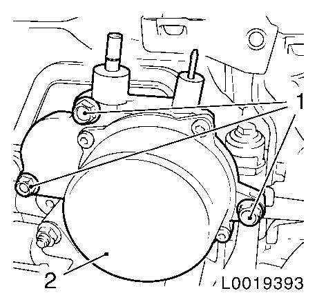
Detach brake servo vacuum line (2) from vacuum pump
|
| 25. |
Detach vacuum hose (1) from vacuum pump
|
|
|
| 26. |
Remove vacuum pump (2)
|
|
|
| 29. |
Lower vehicle by its full height
|
| 30. |
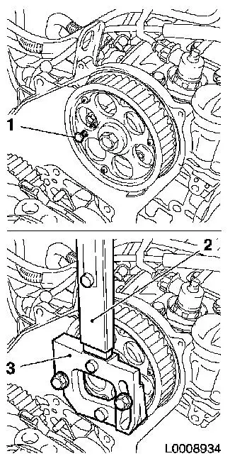
Remove camshaft sprocket
| • |
Remove TDC fixing bolt (1)
| – |
Unscrew bolt
Note: Counterhold it
with KM-6347 (3) together with KM-956-1 (2)
|
|
|
|
|
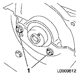
| 31. |
Detach rear toothed belt cover from camshaft housing
|
|
|
|
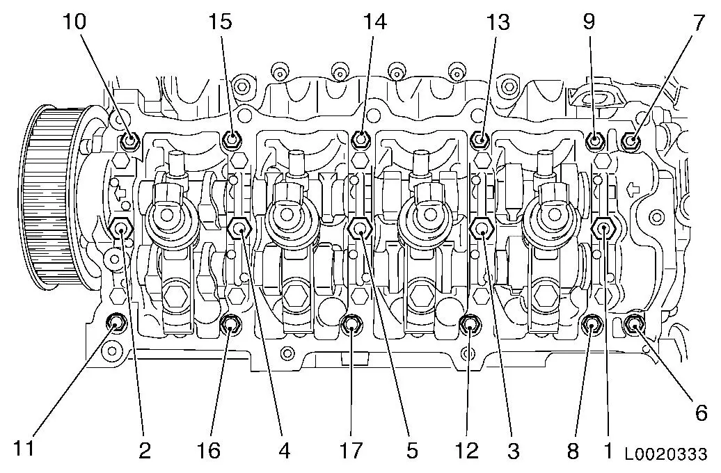
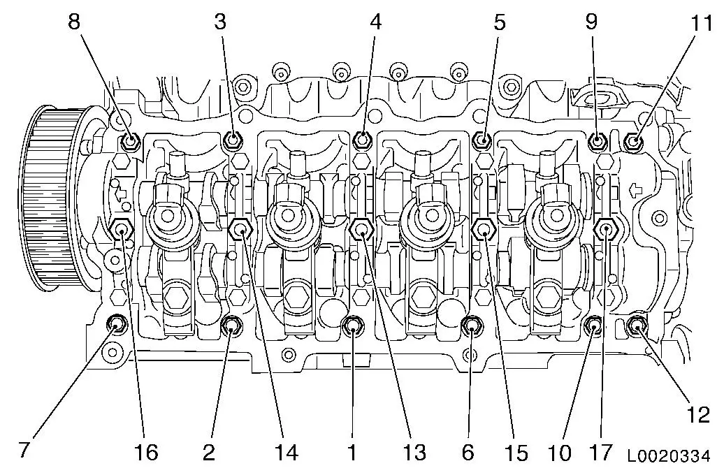
| 32. |
Remove camshaft housing
| • |
Unscrew 17x bolts in the specified sequence
Note: Slacken the bolt
half a turn and then unscrew
|
|
|
| 33. |
Remove camshaft bearing cap 5 (1)
|
|
|
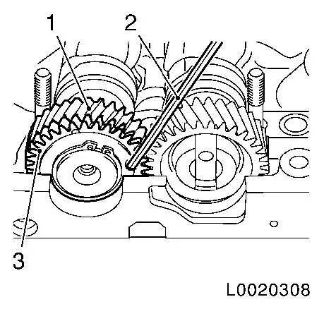
| 34. |
Lock exhaust camshaft gear wheels
| • |
Lock balancer gear wheel, exhaust camshaft (3), with balancer
camshaft gear wheel (1) with KM-6092-10
(2) so that it cannot twist
|
|
|
|
| 35. |
Remove 2x camshafts
Note: Note marking
before dismantling camshaft bearing cap
| • |
Release the camshaft bearing caps in the order specified,
working in a spiral pattern in stages of 1/2 to 1 turn
Note: When replacing
the exhaust camshaft, the balancer gear wheel (2) must be
pre-tensioned with KM-6092 (1) and
connected to the gear wheel of the exhaust camshaft (3) with fixing
pin KM-6092-10 (4)
|
|
|
|
| 36. |
Remove camshaft seal ring (1)
|
|
|
 Install
| 37. |
Clean sealing surface
| • |
Camshaft housing, camshaft bearing caps
|
|
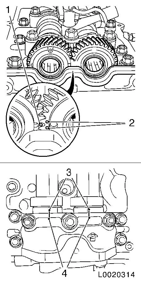
Important: When installing the
camshafts, ensure that the mark (1) on the exhaust camshaft gear
wheel is between the two marks (2) on the intake camshaft gear
wheel and that the marks on the camshaft bearing cap (4) are in
line with the two marks on the camshafts (3)
|
| 38. |
Insert 2x camshafts
| • |
Insert camshaft in camshaft housing
Note: Coat bearing
positions with engine oil
|
|
|
|
|
| 39. |
Tighten 2x camshafts
Note: Coat bearing
positions with engine oil
| • |
Attach camshaft bearing caps 1 - 4 to camshaft housing
Note: Arrows on bearing
caps point towards engine timing side
|
| • |
Attach camshaft bearing cap 5
| – |
Remove KM-6092-10 from exhaust
camshaft gear wheel
|
|
| • |
Tighten the camshaft bearing caps in the order specified (1 -
15) in stages of 1/2 to 1 turn
|
|
|
| 40. |
Insert camshaft seal ring
| • |
Drive in flush using KM-656 (1)
|
|
|
|
|
| 41. |
Install camshaft housing
| • |
Tighten 17x bolts in the specified tightening sequence
(1-17)
| – |
Tighten 12x bolt (M8) 22 Nm
|
| – |
Tighten 5x bolt (M10) 27 Nm
Note: Coat bolts with
engine oil
|
|
|
|
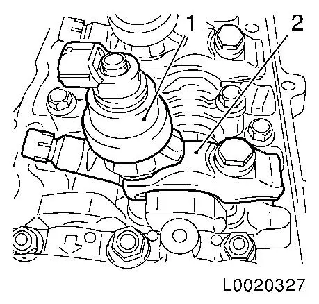
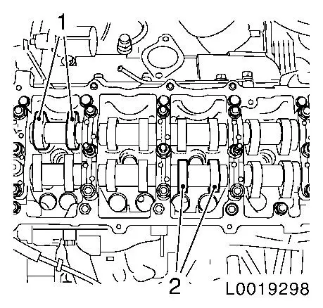
| 42. |
Turn the camshaft until the cam pair (1) and (2) faces
upwards.
|
|
|
| 43. |
Check valve clearances and adjust if necessary 
|
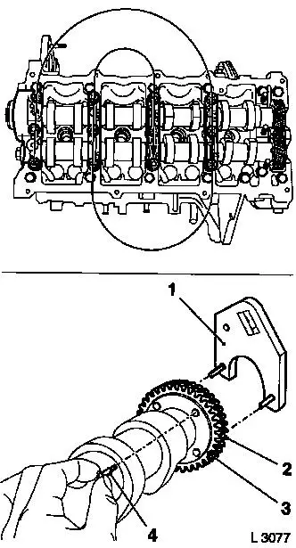
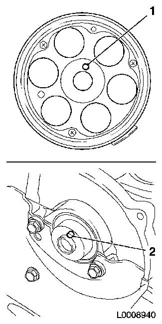
| 44. |
Install camshaft sprocket
Note: Camshaft journal
(2) must engage in the bore (1) in the camshaft sprocket
| • |
Tighten bolt 111 Nm
| – |
Counterhold with KM-6347 in
conjunction with KM-956-1
|
|
Important: Do not damage
increment disc
|
| • |
Screw in TDC fixing bolt
|
|
|
|
| 45. |
Raise vehicle by its full height
|
| 47. |
Install vacuum pump
Note: Pay attention to
position of teeth
| • |
Tighten 3x bolt 24 Nm
Note: Note guide
sleeves
|
|
| 48. |
Attach vacuum hose to vacuum pump
|
Important: Quick-release fitting
must audibly engage
|
| 49. |
Attach brake servo vacuum line to vacuum pump
|
| 50. |
Install intake pipe together with throttle valve module
| • |
Connect wiring harness plug, throttle valve module
|
| • |
Install intake pipe lower bracket
|
|
| 51. |
Attach intake pipe bracket to intake pipe
|
| 52. |
Attach charge air hose for throttle valve connection
|
| 53. |
Install EGR valve
| • |
Tighten 4x bolts 24 Nm
Note: Attach coolant
hose bracket
|
| • |
Attach exhaust gas recirculation cooler pipe
|
|
| 54. |
Attach coolant hose to thermostat housing.
|
| 55. |
Install 4x injector
| • |
Install 4x brackets
| – |
Align injectors with EN-48560 (1)
|
| – |
Tighten 4x bolt in three stages
|
|
|
|
|
| 56. |
Clean sealing surface
|
|
Important: Oil return bore (2)
may not be covered with adhesive sealing compound
|
| 57. |
Apply sealing compound
Note: Select a suitable
sealing compound from the replacement parts catalogue
| • |
Apply adhesive sealing compound to sealing surfaces (1) and
(3)
|
|
|
| 58. |
Install camshaft housing cover
| • |
Detach 4x EN-48559 from injector
|
| • |
Tighten 10x bolts 10 Nm
|
| • |
Install 4x injector seals
|
|
| 59. |
Install 4x high-pressure lines
Note: Attach first to
injector, then to pressure chamber
| • |
Detach 4x sealing caps from pressure chamber
|
| • |
Tighten 8x union nut 25 Nm
|
|
| 60. |
Connect engine management wiring harness plugs
| • |
Connect 14x wiring harness plugs
| – |
Coolant temperature sensor
|
|
| • |
Clip in 2x wiring harnesses
|
|
| 61. |
Attach engine management wiring trough to camshaft housing
cover
|
| 62. |
Attach vacuum hose to wastegate unit for exhaust gas
recirculation cooler
|
| 63. |
Attach charge air pipe to camshaft housing cover
| • |
Attach camshaft vent hose to charge air pipe
|
| • |
Clip in hose for wastegate unit of exhaust gas recirculation
cooler bypass valve
|
|
| 64. |
Attach fuel return line to injector
| • |
Fasten 4x retaining clamps
|
|
| 65. |
Connect engine timing wiring harness (top)
| • |
Attach positive cable to fuse carrier
Note: Pay attention to
installation position
|
| • |
Connect and lock wiring harness plug
|
|
| 66. |
Raise vehicle by half its height
|
| 67. |
Attach wiring harness to engine control unit
| • |
Connect wiring harness plug to control unit and lock
|
| • |
Clip wiring harness into bracket
|
| • |
Clip 3x wiring harnesses to engine
|
|
| 68. |
Lower vehicle by half its height
|
| 69. |
Install battery holder
| • |
Clip in wiring harness plug
|
| • |
Attach wiring harness
| – |
Clip 2x to battery support
|
|
| • |
Clip in bracket for coolant hose
|
| • |
Clip in control unit of pre-heating system
|
|
| 70. |
Install battery
| • |
Attach positive connection to positive terminal
|
|
| 71. |
Connect battery
| • |
Attach ground cable to ground terminal
|
|
| 72. |
Install air intake pipe.
|
Important: Wear protective
goggles
|
| 73. |
Carry out leak test on high pressure system
Note: Engine must be at
operating temperature
| • |
Carry out actuator test (fuel leak)
|
| • |
Visual inspection of high pressure system for fuel leak
|
|
| 74. |
Program volatile memories
|
| 76. |
Install air cleaner housing
|
|
