|
Replace intake manifold
Important: When
working on the fuel system maintaining cleanliness is essential, as
even the smallest of dirt particles may result in engine operating
faults or fuel system faults. Open fuel connections must be sealed
off with suitable sealing plugs from the Opel parts catalogue.
Sealing plugs are designed for single use only.
 Remove Remove
| 2. |
Disconnect battery
| • |
Detach negative connection from ground terminal
|
|
| 3. |
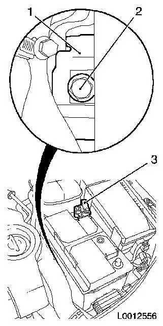
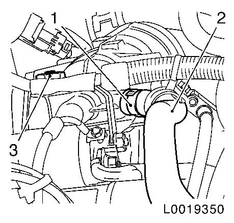
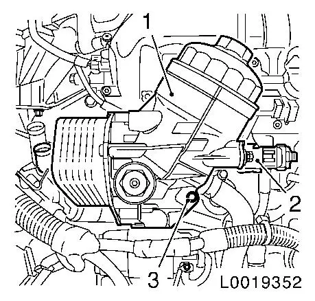
Remove battery
| • |
Detach positive terminal (3) from positive pole
|
|
|
|
| 4. |
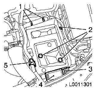
Remove battery support.
| • |
Unclip control unit of pre-heating system (4)
|
| • |
Unclip coolant hose bracket (5)
|
| • |
Detach wiring harness
| – |
Unclip 2x from battery support (1)
|
|
| • |
Unclip wiring harness plug (3)
|
|
|
|
Warning: The cooling system is
pressurised. Open the closure cap carefully
|
| 5. |
Unscrew coolant expansion tank closure cap
|
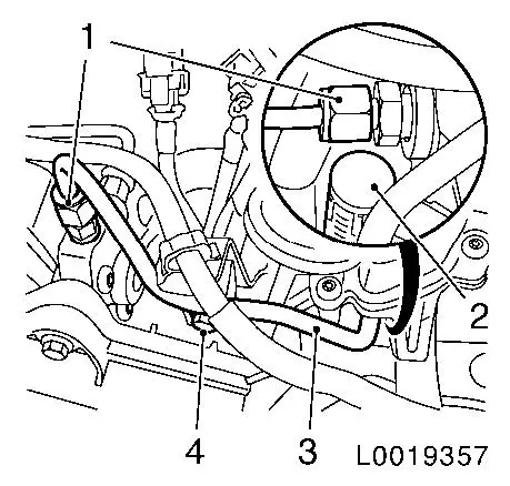
| 7. |
Detach fuel return line (2)
|
|
|
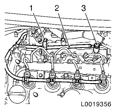
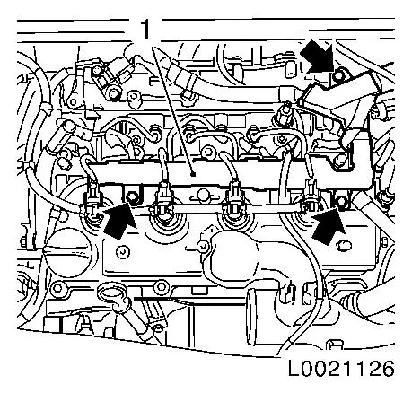
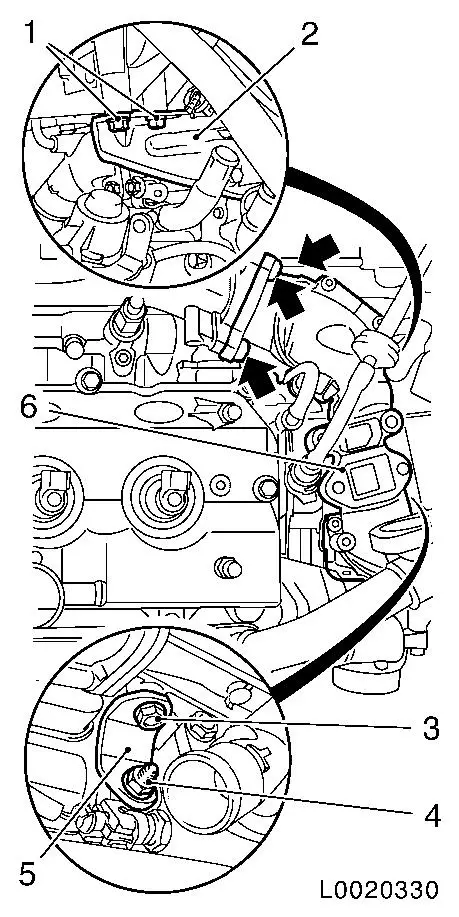
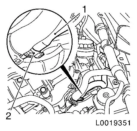
| 8. |
Remove high-pressure line (3) from high pressure pump to
pressure chamber
| • |
Disconnect wiring harness plug, sheathed glow plug (2) of
cylinder 1
Note: Release wiring
harness plug with EN-48558 and pull off
by hand
|
| • |
Unscrew 2x union nuts (1)
|
| • |
Seal off connections with sealing caps
|
|
|
|
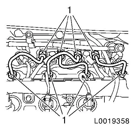
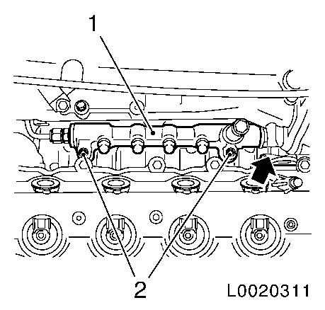
| 9. |
Detach 4x high-pressure lines from pressure chamber to
injector
| • |
Unscrew 8x union nut (1)
|
| • |
Seal off connections on pressure chamber with suitable sealing
plugs
|
| • |
Seal off connections on injectors with EN-48559
|
|
|
|
| 10. |
Detach vacuum hose (1) of wastegate unit for exhaust gas
recirculation cooler
|
|

|
| 11. |
Detach engine management wiring trough (1) from camshaft
housing cover
| • |
Unscrew 3 bolts (arrows)
|
|
|
|
| 12. |
Disconnect engine management wiring harness plugs
| • |
Disconnect 12x wiring harness plugs
| – |
3x sheathed glow plugs
Note: Release with
EN-48558 and pull off by hand
|
| – |
Coolant temperature sensor
|
|
| • |
Unclip 2x wiring harnesses
|
|
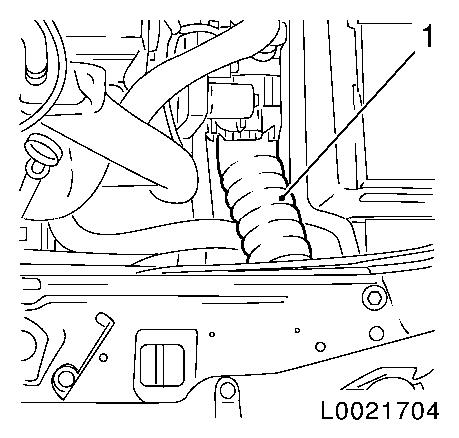
| 13. |
Detach charge air hose for throttle valve connection (1)
|
|
|
| 14. |
Remove exhaust gas recirculation valve (1)
| • |
Disconnect wiring harness connector.
|
| • |
Detach EGR cooler pipe (2)
|
|
|
|
| 15. |
Detach intake pipe rear bracket (2) from intake pipe (6)
|
| 16. |
Remove intake pipe together with throttle valve module
| • |
Disconnect wiring harness plug for throttle valve module
|
| • |
Remove intake pipe lower bracket (5)
|
| • |
Unscrew 3 bolts (arrows)
|
|
|
|
| 17. |
Remove intake pipe rear bracket
|
| 18. |
Remove accumulator (1)
| • |
Disconnect wiring harness plug (arrow)
|
|
|
|
| 19. |
Raise vehicle by its full height
|
| 20. |
Place collecting basin underneath.
|
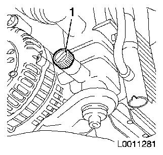
| 21. |
Drain coolant
| • |
Open drain bolt on radiator (1)
|
|
|
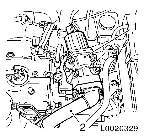
|
| 22. |
Detach oil return hose (2)
|
| 23. |
Release oil filter housing with heat exchanger
|
|
|
| 24. |
Lower vehicle by its full height
|
| 25. |
Detach coolant hose (1) from heat exchanger
|
|
|
| 26. |
Remove oil filter housing with heat exchanger (1)
| • |
Disconnect wiring harness plug (2)
|
| • |
Unclip 2x wiring harnesses
|
|
|
|
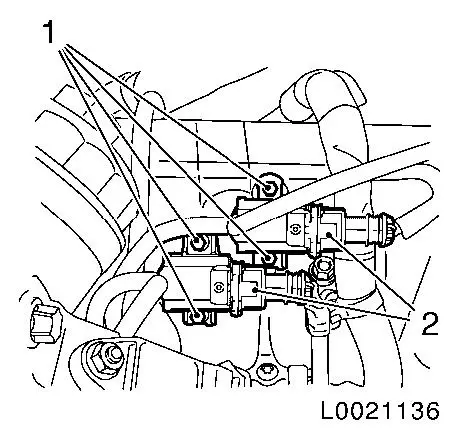
| 27. |
Detach 2x solenoid valves
| • |
Disconnect 2x wiring harness plugs (2)
|
| • |
Unclip 4x vacuum hoses from intake manifold
|
|
|
|
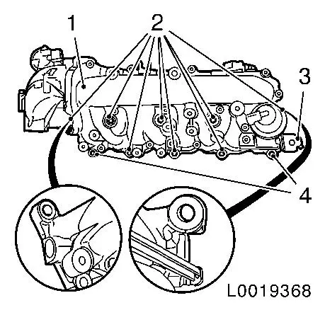
| 28. |
Remove intake manifold (1)
| • |
Detach wiring harness from intake manifold
|
| • |
Unclip fuel return line from bracket (3)
|
| • |
Detach hose from vacuum unit
|
| • |
Unscrew 8x bolts (2)
Note: Note different
bolt lengths
|
|
|
|
| 29. |
Detach intake air temperature sensor
|
 Install
| 30. |
Attach intake air temperature sensor
|
| 31. |
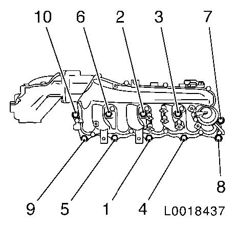
Install intake manifold
Note: Tighten in the
specified tightening sequence (1-10)
| • |
Tighten 8x bolts 24 Nm
Note: Note different
bolt lengths
|
| • |
Clip in 5x vacuum hoses
|
| • |
Attach wiring harness to intake manifold
|
| • |
Clip in fuel return line
|
| • |
Attach hose to vacuum unit
|
|
|
|
| 32. |
Attach 2x solenoid valves
| • |
Connect 2x wiring harness plugs
|
| • |
Clip 4x vacuum hoses to intake manifold
|
|
| 33. |
Install oil filter housing with heat exchanger
| • |
Fix wiring harness plug
|
| • |
Clip in 2x wiring harnesses
|
|
| 34. |
Attach coolant hose to heat exchanger
|
| 35. |
Raise vehicle by its full height
|
| 36. |
Fasten oil filter housing with heat exchanger
| • |
Tighten banjo bolt 110 Nm
|
|
| 37. |
Attach oil return hose
|
| 38. |
Lower vehicle by its full height
|
| 39. |
Install accumulator
| • |
Fix wiring harness plug
|
|
| 40. |
Install intake pipe rear bracket
|
| 41. |
Install intake pipe together with throttle valve module
| • |
Connect wiring harness plug, throttle valve module
|
| • |
Install intake pipe lower bracket
|
|
| 42. |
Attach intake pipe bracket to intake pipe
|
| 43. |
Install exhaust gas recirculation valve
| • |
Tighten 4x bolts 24 Nm
Note: Attach coolant
hose bracket
|
| • |
Attach exhaust gas recirculation cooler pipe
|
| • |
Fix wiring harness plug
|
|
| 44. |
Attach charge air hose for throttle valve connection
|
| 45. |
Connect engine management wiring harness plugs
| • |
Connect 12x wiring harness plugs
| – |
Coolant temperature sensor
|
|
| • |
Clip in 2x wiring harnesses
|
|
| 46. |
Attach engine management wiring trough to camshaft housing
cover
|
| 47. |
Attach vacuum hose to wastegate unit for exhaust gas
recirculation cooler
|
| 48. |
Install 4x high-pressure lines from pressure chamber to
injectors
Note: Attach first to
injector, then to pressure chamber
| • |
Detach 4x sealing caps from pressure chamber
|
| • |
Detach 4x EN-48559 from injector
|
| • |
Tighten 8x union nut 25 Nm
|
|
| 49. |
Attach high-pressure line from high pressure pump to pressure
chamber
| • |
Attach union nut to pressure chamber with MKM-6600-207 and to high-pressure pump with MKM-6600-12 and MKM-6600-308
| – |
Tighten 2x union nuts 25 Nm
|
|
| • |
Connect wiring harness plug, sheathed glow plug of cylinder
1
|
|
| 50. |
Attach fuel return line
| • |
Tighten banjo bolt 10 Nm
|
|
| 51. |
Check and correct engine oil level
|
| 52. |
Install battery holder
| • |
Clip in wiring harness plug
|
| • |
Attach wiring harness
| – |
Clip 2x to battery support
|
|
| • |
Clip in bracket for coolant hose
|
| • |
Clip in control unit of pre-heating system
|
|
| 53. |
Install battery
| • |
Attach positive connection to positive terminal
|
|
| 54. |
Connect battery
| • |
Attach negative connection to ground terminal
|
|
Important: Wear protective
goggles
|
| 55. |
Carry out leak test on high pressure system
Note: Engine must be at
operating temperature
| • |
Carry out actuator test (fuel leak)
|
| • |
Visual inspection of high pressure system for fuel leak
|
|
| 57. |
Program volatile memories
|
| 58. |
Fill and bleed cooling system 
|
|
