|
Engine maintenance using a section engine
 Remove Remove
| 1. |
Remove manual transmission from engine 
|
| 2. |
Place collecting basin underneath.
|
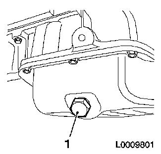
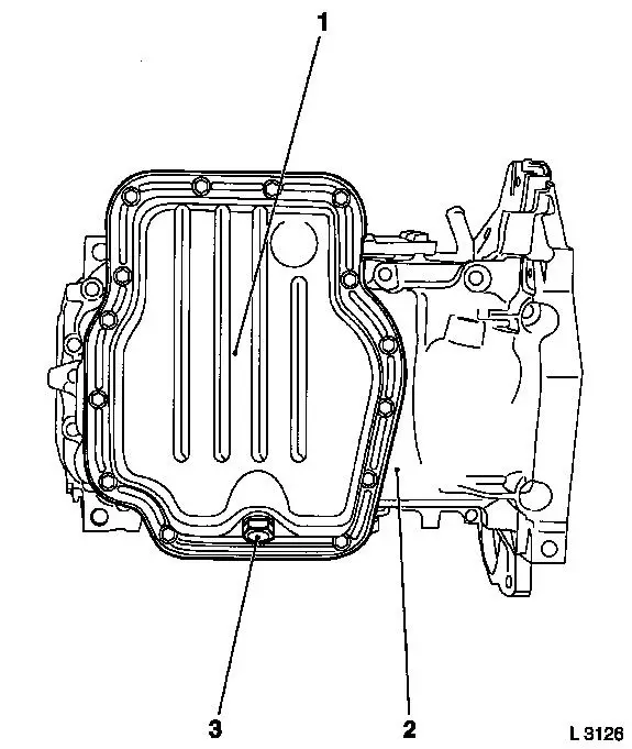
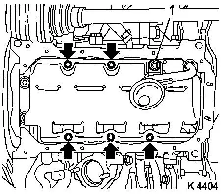
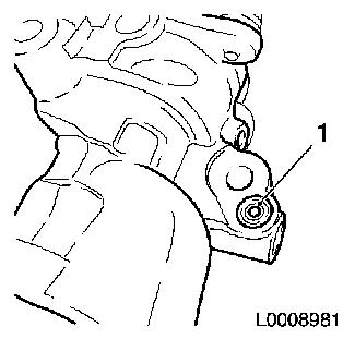
| 3. |
Drain engine oil
| • |
Unscrew oil drain bolt (1)
|
|
|
|
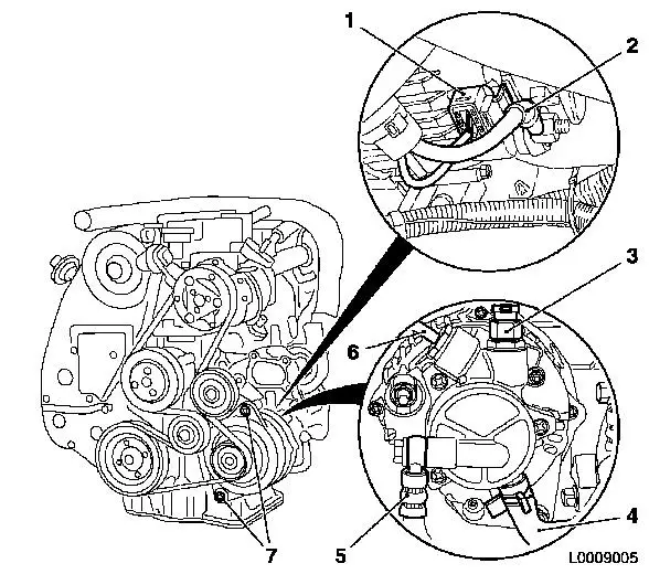
| 4. |
Attach engine timing wiring harness
| • |
Disconnect wiring harness plug of:
| – |
Change-over valves for solenoid valve
|
| – |
Sensor for change-over valves
|
| – |
Alternator wiring harness plug
|
| – |
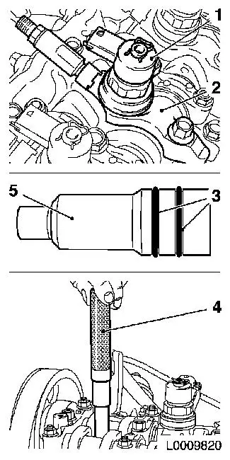
Crankshaft pulse pick-up
|
|
|
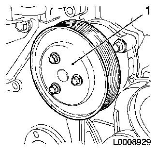
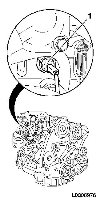
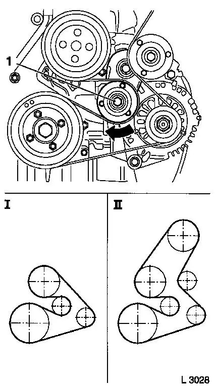
| 5. |
Remove ribbed V-belt
| • |
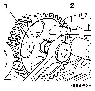
Mark direction of rotation
|
| • |
Apply tension to ribbed V-belt tensioner via bolt (1) in the
direction of the arrow
|
| • |
Fix ribbed V-belt tensioner to bore (2)
|
|
|
|
| 6. |
Detach wiring harness from starter alternator
| • |
Detach from alternator
| – |
Disconnect wiring harness connector.
|
|
| • |
Unscrew oil pressure switch
|
| • |
Remove coolant temperature sensor
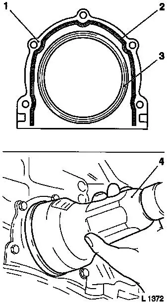
|
|
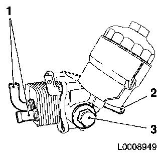
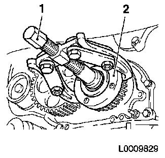
| 7. |
Remove compressor (1)
| • |
Unscrew 3 bolts
Note: Note different
bolt lengths
|
|
|
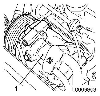
|
|
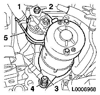
| 8. |
Remove alternator
| • |
Detach vacuum line - solenoid valves (6)
|
| • |
Disconnect electrical connection (2)
|
| • |
Disconnect wiring harness plug (1)
|
| • |
Remove brake force amplifier vacuum line (3)
|
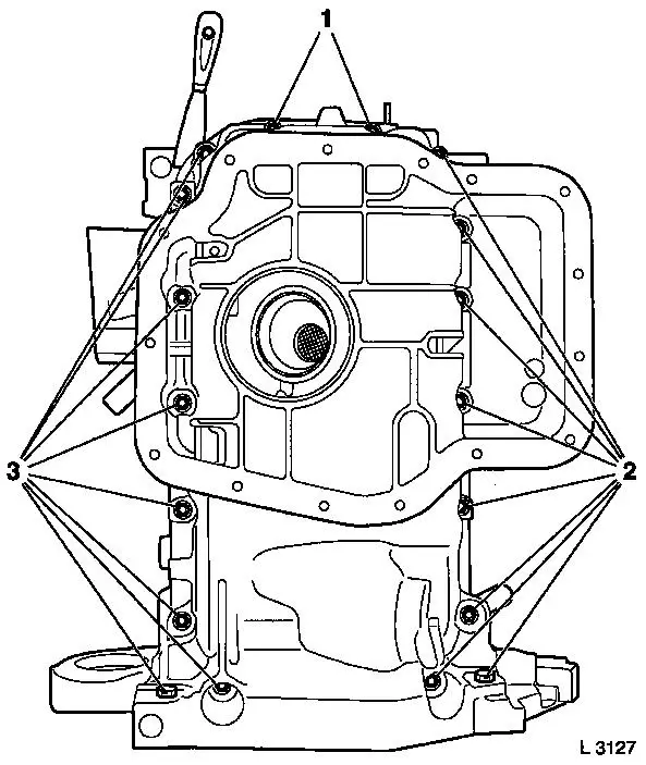
| • |
Detach oil feed line, vacuum pump (5)
|
| • |
Detach oil return hose, vacuum pump (4)
|
|
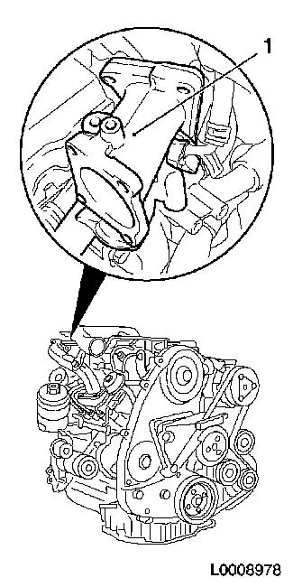
|
| 9. |
Detach alternator support
|
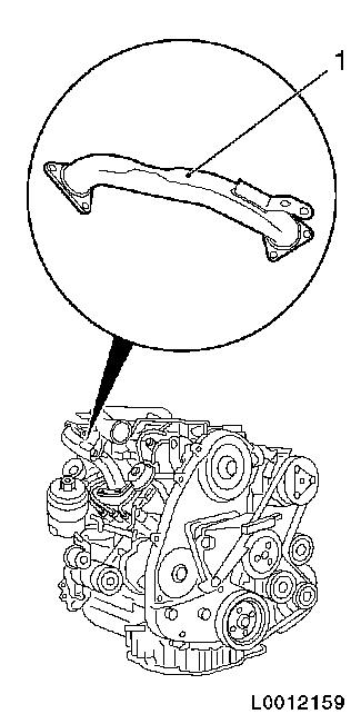
| 10. |
Remove air intake manifold (1)
|
|
|
| 11. |
Detach oil dipstick guide tube with bracket
| • |
Detach from upper part of oil pan
|
| • |
Detach from camshaft housing
|
|
| 12. |
Remove EGR cooler -
| • |
Detach from intake manifold
|
| • |
Detach from exhaust gas recirculation port
|
| • |
Detach from camshaft housing
|
|
|
|
| 13. |
Disconnect vacuum hose (2) from turbocharger control unit
(1)
|
|
|
| 14. |
Detach oil return hose from cylinder block
|
| 15. |
Remove exhaust manifold heat shield
|
|
|
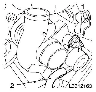
| 16. |
Detach turbocharger oil feed line
| • |
Detach from turbocharger
|
| • |
Detach from cylinder block
|
|
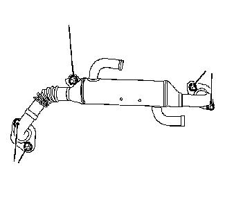
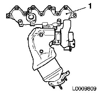
| 17. |
Remove exhaust manifold (1) with turbocharger
| • |
Remove from cylinder head
|
| • |
Detach from catalytic converter bracket
|
|
|
|
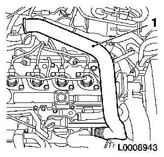
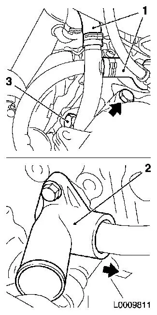
| 18. |
Detach 2x coolant hoses (1)
|
| 19. |
Remove coolant pipe
| • |
Detach from cylinder block
|
| • |
Pull out of coolant flange (2) in direction of arrow
|
|
|
|
| 20. |
Remove coolant discharge port
|
|
|
| 21. |
Detach bracket, throttle valve body (1), from camshaft
housing
|
|
|
| 22. |
Remove oil filter housing with heat exchanger
| • |
Detach 2x coolant hoses from coolant port (1)
|
| • |
Detach oil return hose from port (2)
|
|
|
|
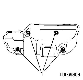
| 23. |
Remove starter
| • |
Detach cable connections
| – |
Unscrew 2x nut (2) and (3)
|
|
| • |
Unscrew upper bolt on the transmission side
|
|
|
|
| 24. |
Remove charge air pipe (1)
|
|
|
| 25. |
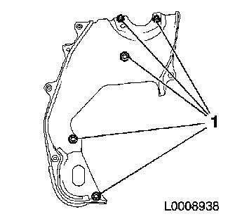
Remove 3x engine transport shackle
|
| 26. |
Remove EGR-port (1)
| • |
Unscrew 2x bolts
Note: Note different
bolt lengths
|
|
|
|
Important: After detaching the
pressure lines, seal off injector and pressure chamber openings
with protective caps
1)
|
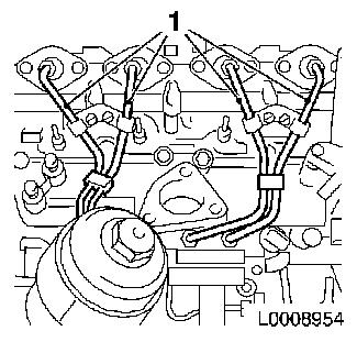
| 27. |
Remove high pressure lines (1), pressure chamber to
injectors
| • |
Unscrew 8x union nut with KM-812 or
KM-6098
|
| • |
Take out pressure lines
|
| • |
Seal 4x pressure chamber opening with protective cap
|
| • |
Seal 4x injector opening with protective cap
|
|
|
|
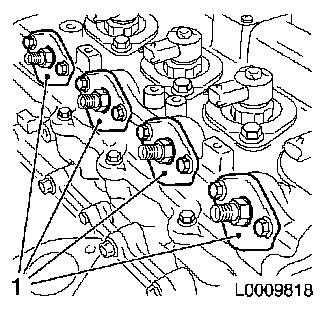
| 28. |
Remove 4x seals, connection for injectors (1)
|
|
|
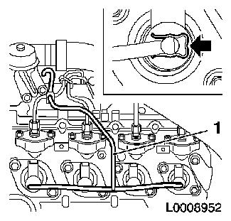
| 29. |
Detach fuel return line (1)
| • |
Detach 4x fuel return line from injector
| – |
Press 4x retaining clamps in direction of arrow
|
|
| • |
Detach fuel return line from pressure chamber
|
| • |
Unscrew 2x bolts
Note: Note different
bolt lengths
|
|
|
|
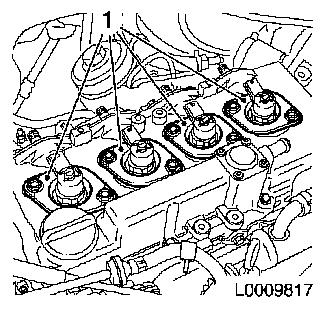
| 30. |
Remove 4x seal, injectors (1)
|
|
|
| 31. |
Remove 4x injector (1)
Note: Mark
injectors
| • |
Remove 4x bracket, injector (2)
| – |
Unscrew 4x bolts
Note: If a heat
protection sleeve (5) also has to be removed when removing an
injector, the gaskets (3) must be replaced and the heat protection
sleeve must be hammered into the cylinder head with KM-6357 (4)
|
|
|
|
|
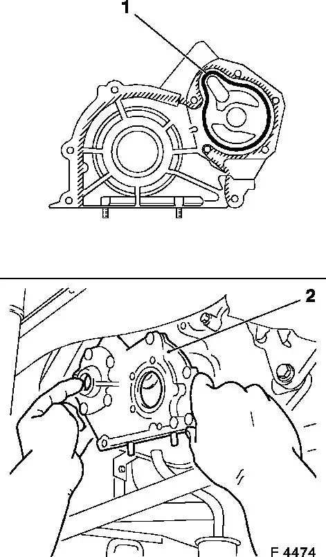
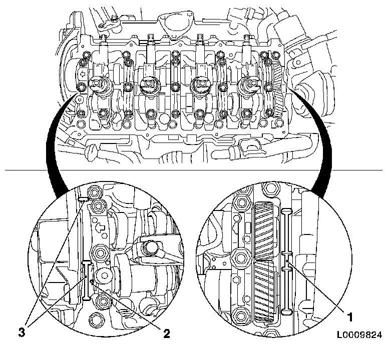
| 32. |
Detach front toothed belt cover (top) (4)
| • |
Unscrew 8x bolts
Note: Note different
bolt lengths
|
| • |
Remove camshaft sensor bracket (1)
|
|
|
|
| 33. |
Detach camshaft sensor with bracket
|
| 34. |
Remove engine damping block support
| • |
Detach from engine damping block bracket
|
| • |
Detach from cylinder block
|
| • |
Remove engine damping block adapter (1)
|
|
|
|
| 35. |
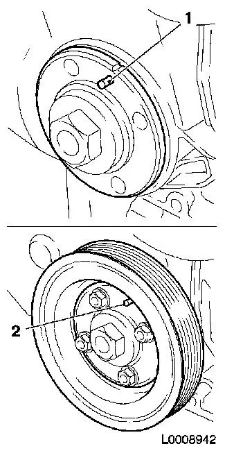
Detach torsional vibration damper (1)
| • |
Unscrew 4x bolts
Note: Counterhold at
bolt (2)
|
|
|
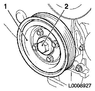
|
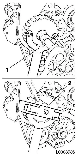
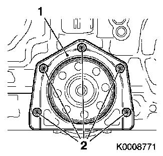
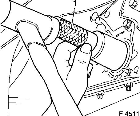
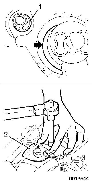
| 36. |
Remove coolant pump drive gear (1)
|
|
|
| 37. |
Remove front toothed belt cover (lower) (1)
|
|
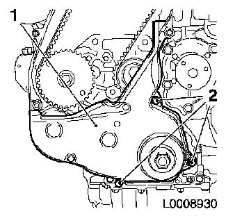
|
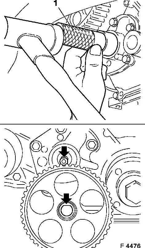
| 38. |
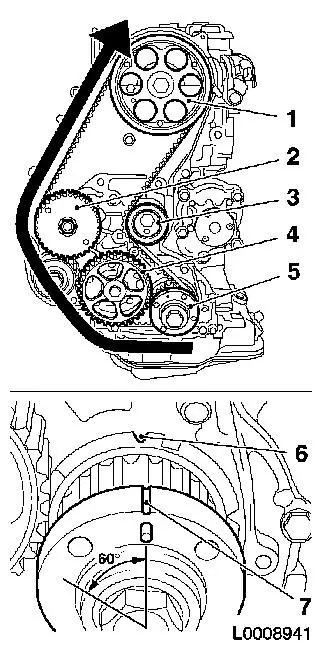
Move crankshaft in direction of engine rotation to "Cylinder
no.1 combustion stroke TDC"
Note: Marking on
toothed belt drive gear must align with projection on oil pump
cover (arrows)
| • |
Fix with TDC fixing bolt (M6) (1) camshaft drive gear
|
| • |
Fix with TDC fixing bolt (M8) (2) high pressure pump gear
|
|
|
|
| 39. |
Remove toothed belt
| • |
Mark direction of rotation
|
| • |
Slacken the toothed belt tension roller
|
| • |
Apply preliminary tension to toothed belt tension roller with
hexagon (2) in direction of arrow
|
| • |
Fix toothed belt tension roller in pre-tensioned position
|
|
|
|
| 40. |
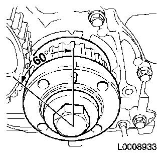
Turn engine 60°against the direction of engine rotation
|
| 41. |
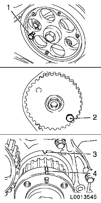
Detach oil pump gear (1)
| • |
Unscrew nut
Note: Counterhold with
socket wrench (2)
|
|
|
|
| 42. |
Remove toothed belt drive gear (2)
| • |
Unscrew bolt
Note: Counterhold with
KM-662-C
|
| • |
Remove toothed belt drive gear with KM-161-B (1)
|
|
|
|
| 43. |
Remove high-pressure pump gear
| • |
Counterhold with KM-6356 (1)
|
| • |
Remove high pressure pump gear with KM-6355 (2)
Note: Counterhold with
KM-6356
|
|
|
|
| 44. |
Remove toothed belt guide roller (1)
|
|
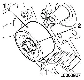
|
| 45. |
Remove rear toothed belt cover
|
|
|
Important: After detaching the
high pressure line, seal the apertures of the high pressure pump
and the pressure chamber with protective caps
1)
|
| 47. |
Remove high pressure line (1) from high pressure pump to
pressure chamber
| • |
Unscrew 2x union nuts
| – |
From pressure chamber with KM-812
|
| – |
From high pressure pump with KM-6098
|
|
| • |
Seal 2x opening with protective cap
|
|
|
|
| 48. |
Detach wiring harness bracket (2) from pressure chamber
|
|
|
| 49. |
Remove pressure chamber (4)
| • |
Detach fuel return line from connection (2)
|
| • |
Unscrew 2x bolts (1)
Note: Note different
lengths of the bolt (3) and spacer sleeves (1)
|
|
|
|
| 50. |
Slacken high pressure pump
| • |
Disconnect wiring harness connector.
|
| • |
Unscrew stud bolts (1) and (2)
|
|
|
|
|
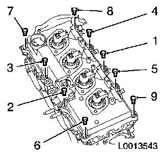
| 51. |
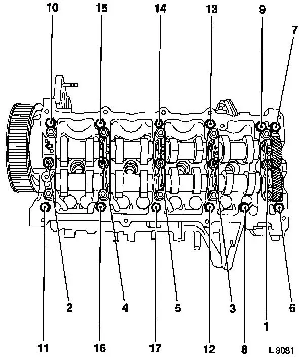
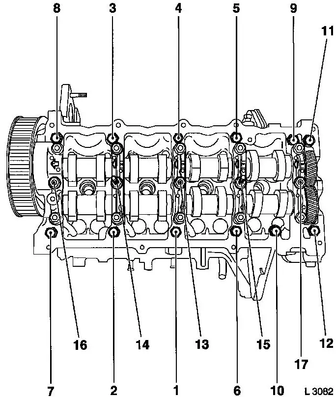
Remove camshaft housing
| • |
Unscrew 17x bolt
| – |
Slacken in the order shown (1 - 17) 1/2 turn and then
remove
|
|
|
|
Important: Mark cup tappet, draw
out of the cylinder head and set aside in order so that the cup
tappets can be allocated to the valves when reinstalled
|
| 53. |
Take out 16x cup tappet (1)
|
|
|
|
| 54. |
Remove cylinder head bolts
| • |
Unscrew 10x bolt
Note: Slacken bolts in
a spiral in the order shown in stages of 1/2 to 1 turn
|
|
|
Important: Place cylinder head on
wooden blocks, be careful of glow plugs
|
| 55. |
Remove cylinder head
Note: Use a second
person
| • |
Remove cylinder head gasket
|
|
| 56. |
Lock flywheel with KM-652
|
| 58. |
Detach clutch pressure plate
|
| 60. |
Using KM-412-A , turn engine through
180°
|
|
| 61. |
Detach lower part of oil pan (1) from upper part of oil pan (2)
with KM-J-37228
|
|
|
| 62. |
Detach upper part of oil pan from cylinder block
| • |
Unscrew bolt (2) and (3)
|
| • |
Separate upper part of oil pan from cylinder block with a broad
spatula
|
|
|
| 63. |
Remove bracket for rear crankshaft seal ring (1)
Important: Note guide sleeves
when removing
|
| • |
Prise out seal ring carefully from cover, rear of
crankshaft
|
|
|
|
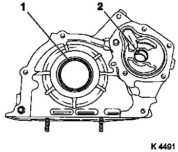
| 64. |
Remove oil pump cover (1)
| • |
Unscrew 9x bolts
Note: Note different
bolt lengths
|
| • |
Remove inner rotor and outer rotor (2)
|
|
|
|
| 65. |
Remove oil intake pipe
|
| 66. |
Remove oil baffle plate
| • |
Unscrew 5x bolt (arrows)
|
|
|
|
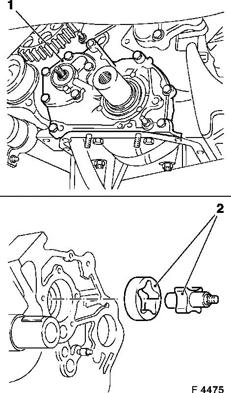
| 67. |
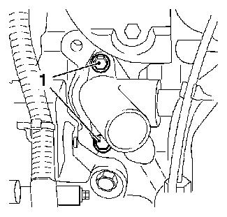
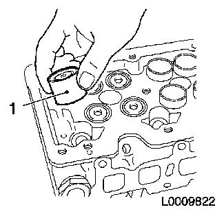
Remove oil pressure switch (1)
|
|
|
| 68. |
Unscrew 2x oil line connection piece
|
| 69. |
Transfer cylinder block
| • |
Detach cylinder block from engine overhaul stand KM-412-A
|
| • |
Detach KM-412-34 KM-412-11-1 from cylinder block
|
| • |
Cylinder Block from Transport Device, Detach and Attach
| – |
Attach KM-412-34 and KM-412-11-1 to cylinder block
|
|
| • |
Attach engine to engine overhaul stand KM-412-A
|
|
| 70. |
Remove plastic insert from coolant pump
|
| 71. |
Clean the components
| • |
Lower part of oil pan, upper part of oil pan, cylinder head,
cylinder block, exhaust manifold, EGR valve, coolant
connections
|
|
 Install
| 72. |
Insert plastic insert in coolant pump
|
| 73. |
Attach centring sleeves
|
| 74. |
Tighten 2x oil line connection piece
|
| 75. |
Tighten oil pressure switch
|
| 76. |
Prise rear crankshaft seal ring (3) out of bracket for rear
crankshaft seal ring (1) with a suitable tool
|
| 77. |
Clean sealing surfaces.
|
| 78. |
Removing seal remains
|
| 79. |
Apply a bead (2) of adhesive sealing compound (black) to the
sealing surfaces of the bracket for the rear crankshaft seal
ring
|
| 80. |
Attach bracket for rear crankshaft seal ring to cylinder
block
| • |
Tighten 5x bolt 9.8 Nm
2)
|
|
| 81. |
Insert new rear crankshaft seal ring into bracket for rear
crankshaft seal ring
|
| 82. |
Drive in rear crankshaft seal ring as far as the stop with
KM-658 (4)
|
|
|
| 83. |
Remove crankshaft seal ring (1)
Important: Do not damage sealing
surfaces
|
| • |
Prise out seal ring with suitable tool
|
|
|
|
| 84. |
Install oil pump cover (2)
Important: Applying the adhesive
sealing compound (black) and the assembly of the oil pump cover
including the torque test must take place within 10 minutes
|
| • |
Apply a bead of adhesive sealing compound (black) to the
sealing surface (cross-hatching) of the oil pump cover
|
| • |
insert inner and outer rotor in cylinder block
|
| • |
Tighten 9x bolt 9.8 Nm
Note: Note different
bolt lengths
|
|
|
|
| 85. |
Install crankshaft seal ring
| • |
Drive in crankshaft seal ring with KM-656 (1) as far as the stop
|
|
|
|
| 86. |
Install oil pump seal ring
| • |
Insert new seal ring in oil pump cover
|
| • |
Drive in as far as the stop with KM-657 (1)
|
|
| 87. |
Fit oil pump drive gear
| • |
At oil pump
Note: Note installation
position (arrow)
|
|
|
|
| 88. |
Install oil baffle plate
|
| 89. |
Install oil intake pipe
|
| 90. |
Install upper part of oil pan
| • |
Apply a bead of silicone sealant (grey) to the sealing surface
of the upper part of the oil pan
|
| • |
Tighten 18x bolt 9.8 Nm
|
|
| 91. |
Remove lower part of oil pan
| • |
Apply a bead of silicone sealant (grey) to the sealing surfaces
of the lower part of the oil pan
|
| • |
Tighten 15x bolt 9.8 Nm
|
|
| 92. |
Using KM-412-A , turn engine through
180°
|
| 93. |
Fit flywheel
| • |
Tighten 8x new bolt 29.4 Nm + 60° +
15°
|
|
| 94. |
Attach clutch pressure plate
| • |
Centre pressure plate with KM-6263
|
|
| 97. |
Cylinder Head, Check for Plane Surface
Note: Check cylinder
head for sag in length and width on the sealing surfaces and for
distortion along the diagonals
|
| 98. |
Insert MKM-571-B (1) in KM-301
(2)
Note: Note
pre-tension
|
|
|
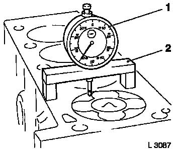
| 99. |
Measure piston projection
| • |
Place probe on cylinder block
|
| • |
Measure piston projection on all 4 pistons
| – |
Perform measurements at two different points (1) and (2) or (3)
and (4)
|
| – |
Determine highest point by turning the crankshaft
|
|
|
|
|
| 100. |
Turn crankshaft 60° against the direction of engine
rotation
|
|
|
|
Important: The largest piston
projection is decisive for the selection of the cylinder head
gasket with the corresponding marking
|
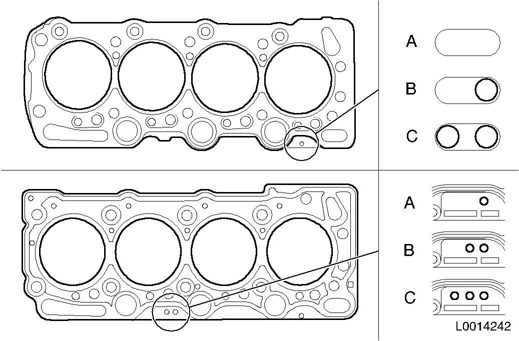
| 101. |
Replace cylinder head gasket
Note: 2 different
designs are available from Aftersales
|
Piston projection
|
Thickness of cylinder head gasket
|
Size
|
Number of holes
|
| |
used
|
New
|
|
Version I
|
Version II
|
|
0.630 - 0.696 mm
|
1.350 mm
|
1.450 mm
|
A
|
-
|
1
|
|
0.697 - 0.763 mm
|
1.400 mm
|
1.500 mm
|
B
|
1
|
2
|
|
0.764 - 0.830 mm
|
1.450 mm
|
1.550 mm
|
C
|
2
|
3
|
| • |
Place cylinder head gasket in position
|
|
|
| 102. |
Position cylinder head
Note: Use a second
person
|
|
Important: Note correct
tightening sequence
|
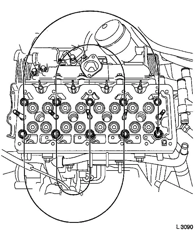
| 103. |
Fasten cylinder head
| • |
Tighten 10x new bolt 39.2 Nm + 60°+
60°
Note: Tighten in the
order shown in a spiral from inside to outside with MKM-610 and KM-470-B
|
|
|
Important: Note marking on cup
tappet
|
| 104. |
Insert 16x cup tappets
|
|
| 105. |
Install camshaft housing
| • |
Attach to cylinder head and tighten in the order shown
(1-17)
| – |
Tighten 12x bolt (M8) 21.6 Nm
|
| – |
Tighten 5x bolt (M10) 26.5 Nm
|
|
|
|
| 106. |
Install high pressure pump
|
| 107. |
Install accumulator
Note: Note different
lengths of the bolt and spacer sleeves
| • |
Attach fuel return line
| – |
From high pressure pump to pressure chamber
|
|
|
| 108. |
Attach wiring harness bracket to pressure chamber
|
| 109. |
Install high pressure line from high pressure pump to
accumulator
| • |
Insert high pressure line
|
| • |
Tighten 2x union nut with KM-812 or
KM-6098 25
Nm
|
|
| 110. |
Attach coolant pump
| • |
Tighten 5x bolt 23.4 Nm
|
|
| 111. |
Replace rear toothed belt cover
|
| 112. |
Insert toothed belt guide roller
|
| 113. |
Fit high pressure pump wheel
Note: Counterhold with
KM-6356
|
| 114. |
Install camshaft sprocket
Note: Camshaft journal
must engage in the bore in the camshaft drive gear
| • |
Tighten bolt 63.7 Nm
Note: Hold using KM-6347
|
| • |
Screw in TDC fixing bolt
|
|
| 115. |
Install oil pump gear
Note: Note installation
position
| • |
Tighten nut
Note: Counterhold with
socket wrench
|
|
| 116. |
Install toothed belt drive gear
| • |
Attach toothed belt drive gear to crankshaft
Note: Note spring
washer
|
| • |
Tighten bolt 196 Nm
Note: Counterhold with
KM-662-C
|
|
| 117. |
Install toothed belt
Note: TDC fixing bolts
must be installed in the high pressure drive gear and camshaft
drive gear and markings (6) and (7) must align
| • |
Position toothed belt
| – |
Toothed belt must be tensioned in the direction of the arrow
from the toothed belt drive gear (5) via the oil pump drive gear
(4) and high pressure pump drive gear (2) to the camshaft sprocket
(1)
|
| – |
Observe direction of rotation
|
|
| • |
Slacken the toothed belt tension roller (3)
|
| • |
Remove 2x TDC fixing bolt
|
| • |
Turn crankshaft 60° against the direction of engine
rotation
|
| • |
Tighten toothed belt tension roller 38.2 Nm
|
|
|
|
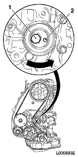
| 118. |
Timing, Check
| • |
Turn crankshaft 6 revolutions in direction of engine rotation
to the adjustment position
|
| • |
The following factors must be present at the adjustment
position
Note: If one of these
factors is not present, the timing must be adjusted
| 1. |
TDC fixing bolt M6 (1) must be able to be inserted
in the camshaft drive gear |
| 2. |
TDC fixing bolt M8 (2) must be able to be inserted
in the high pressure pump drive gear |
| 3. |
Marking (4) on the toothed belt drive gear must
align with the marking (3) on the oil pump housing cover |
|
| • |
Remove 2x TDC fixing bolt
|
|
|
|
| 119. |
Install front toothed belt cover (lower)
|
| 120. |
Install coolant pump drive gear
| • |
Tighten 3x bolt 12.3 Nm
|
|
Important: Journal (1) of toothed
belt drive gear must engage in the bore (2) of the torsional
vibration damper
|
| 121. |
Install torsional vibration damper
| • |
Tighten 4x bolt 19.6 Nm
Note: Counterhold
against bolt, toothed belt drive gear
|
|
|
|
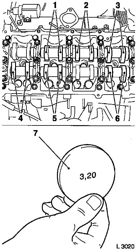
| 122. |
Turn the crankshaft until the cam pair (1) and (2) faces
upwards.
|
| 123. |
Check valve lash with feeler gauge
Note: Valve lash must
be checked at room temperature when the engine is cold.
| • |
Test values: Intake valve/exhaust valve (0.35 - 0.45 mm)
|
|
| 124. |
Adjust valve play
| • |
Turn the bucket tappet until the tappet groove faces
outwards
|
Important: Care should be taken
that the valves do not strike the piston head
|
| • |
Press down cup tappet with KM-6090
Note: Note different
tool designs for intake and exhaust valve
| – |
Marking - IN = intake side
|
| – |
Marking - EX = exhaust side
|
|
|
|
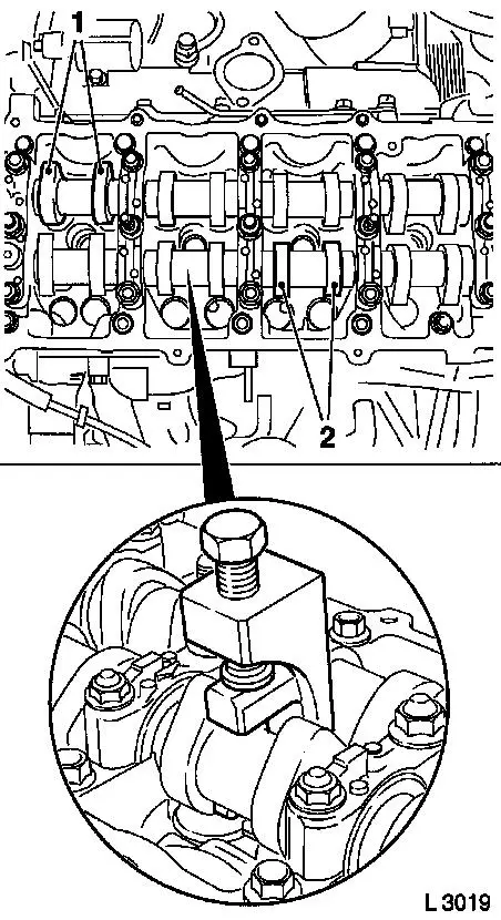
|
| 125. |
Example for determination of shim thickness:
|
1.
|
Thickness of installed shim
|
|
3.15 mm
|
|
2.
|
Measurement between cams and cup tappets
|
+
|
0.45 mm
|
|
|
|
=
|
3.60 mm
|
|
3.
|
Nominal valve play
|
-
|
0.40 mm
|
|
4.
|
Thickness of new shim
|
=
|
3.20 mm
|
|
| 126. |
Insert shim
| • |
Coat new shim (7) with engine oil and insert in cup tappet with
code facing down
|
|
| 127. |
Check and adjust remaining valves
| • |
Turn crankshaft 180° in the direction of rotation of the
engine
| – |
Check and adjust valve pair (6) and (2)
|
|
| • |
Turn crankshaft 180° in the direction of rotation of the
engine
| – |
Check and adjust valve pair (5) and (3)
|
|
| • |
Turn crankshaft 180° in the direction of rotation of the
engine
| – |
Check and adjust valve pair (4) and (1)
Note: Valve lash must
be checked again on all adjusted valves
|
|
|
|
|
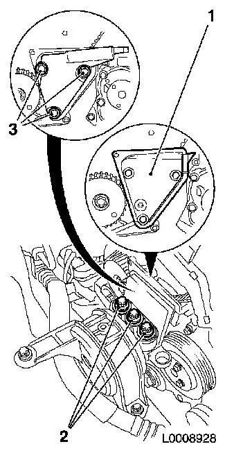
| 128. |
Install engine damping block bracket
| • |
Insert engine damping block adapter
|
| • |
Attach engine damping block support to cylinder block
|
| • |
Engine damping block support to engine damping block
bracket
|
|
| 129. |
Install front toothed belt cover (top)
| • |
Tighten 8x bolt 9.8 Nm
Note: Note different
bolt lengths
|
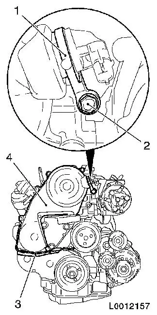
| • |
Install camshaft sensor bracket
|
| • |
Attach vacuum line to toothed belt cover
|
|
| 130. |
Replace 2x seals, injector
|
|
|
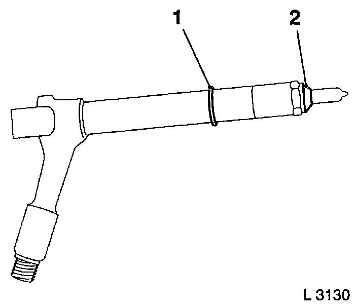
| 131. |
Install 4x injector
| • |
Tighten 4x bolt in three stages
| 1. |
Tighten bolt 40 Nm
|
| 2. |
Loosen bolt |
| 3. |
Tighten bolt 32 Nm
|
|
|
|
|
|
| 132. |
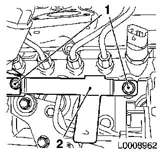
Apply sealing compound
Important: Oil return bore (2)
may not be covered with adhesive sealing compound
|
| • |
Apply adhesive sealing compound (white) to sealing surfaces (1)
and (3)
|
|
|
| 133. |
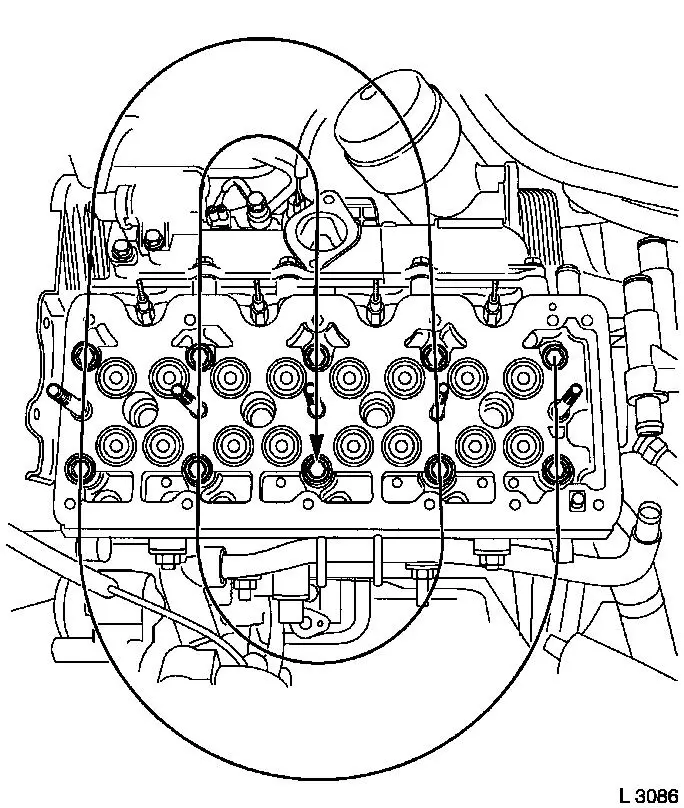
Install camshaft housing cover
| • |
Tighten 9x bolt in the stated order (1...9) 9.8 Nm
|
|
|
|
| 134. |
Install 4x new seal, injectors (2)
| • |
Align seal for injectors
Note: Sealing lip of
seal must be in full contact with the injector with no gaps
(arrow)
|
| • |
Coat 8x bolt head contact surface (1) with special grease
(white)
|
| • |
Tighten injector seal in 2 stages
Note: During the
tightening process, press injector seal against the camshaft
housing cover with your hand
| 1. |
Tighten 2x bolt 10
Nm |
| 2. |
Tighten 2x bolt 19
Nm |
|
|
|
|
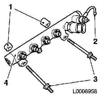
| 135. |
Install 4x new seal, connection for injectors
Note: Marking "UP" must
point upwards
|
|
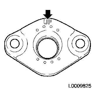
|
| 136. |
Install fuel return line
Note: Note different
bolt lengths
| • |
Attach 4x fuel return line to injector
|
| • |
Attach fuel return line to accumulator
|
|
Important: Pressure lines must be
installed so that they are not under tension
|
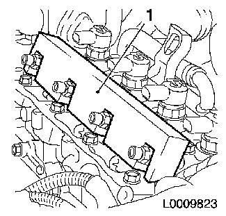
| 137. |
Install 4x high-pressure lines from pressure chamber to
injectors
| • |
Remove 8x protective cap
|
| • |
Attach pressure lines to injector and pressure chamber
| – |
Tighten 8x union nut 25 Nm
|
|
|
Important: Seal ring (1) may not
be displaced on installation
|
| 138. |
Install EGR-port
| • |
Tighten 2x bolt 24 Nm
Note: Note different
bolt lengths
|
| • |
Attach EGR cooler -
| – |
Tighten 2x bolts 28.5 Nm
|
|
|
|
|
| 139. |
Install 3x engine transport shackle
|
| 141. |
Install starter
| • |
Tighten lower bolt 38.2 Nm
|
| • |
Tighten upper bolt 60 Nm
|
| • |
Attach cable connections
|
|
| 142. |
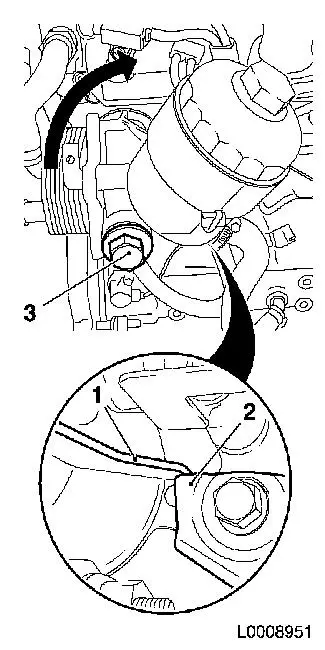
Install oil filter housing
| • |
Replace 2x gaskets
| – |
Oil filter housing to cylinder block
|
| – |
Bolt, oil filter housing
|
|
Important: Turn oil filter
housing in direction of arrow until projection (1) is in contact
with bracket (2)
|
| • |
Tighten bolt (3) 110 Nm
|
| • |
Attach oil return hose to oil pan
|
| • |
Attach 2x coolant hose to coolant port
|
|
|
|
| 143. |
Attach throttle valve body bracket to camshaft housing
|
| 144. |
Attach coolant discharge port
Note: Use sealant
(grey)
|
| 145. |
Install coolant pipe
| • |
Install in coolant flange
|
| • |
Attach to cylinder block
|
|
| 146. |
Attach exhaust manifold with turbocharger
| • |
Attach to catalytic converter bracket
|
|
| 147. |
Install turbocharger oil feed line
| • |
Attach to turbocharger
| – |
Tighten banjo bolt 27.5 Nm
|
|
| • |
Attach to cylinder block
|
|
| 148. |
Attach exhaust manifold heat shield
| • |
Tighten 4x bolt 11.7 Nm
|
|
| 149. |
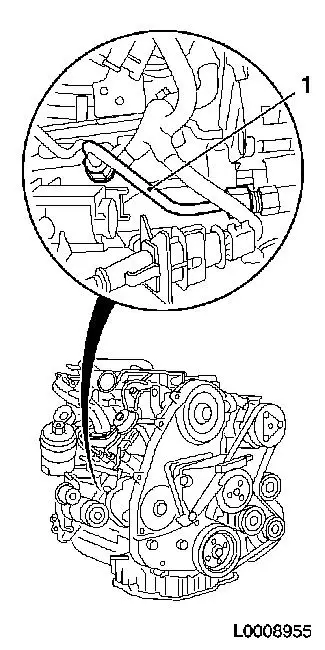
Attach vacuum hose to turbocharger control unit
|
| 150. |
Attach EGR cooler -
| • |
Attach to exhaust manifold
| – |
Tighten 2x bolts 28.5 Nm
|
|
| • |
Attach to exhaust gas recirculation port
| – |
Tighten 2x bolts 28.5 Nm
|
|
| • |
Attach to camshaft housing
|
|
| 151. |
Install dipstick guide tube
| • |
On upper part of oil pan
|
| • |
Attach to camshaft housing
|
|
| 152. |
Attach oil return hose to cylinder block
|
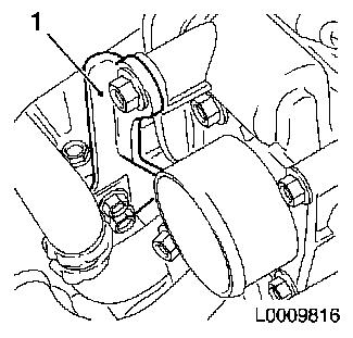
| 153. |
Attach alternator support
|
| 154. |
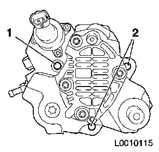
Install alternator
| • |
Tighten 2x bolts
| – |
Tightening torque (M8) 18.6 Nm
|
| – |
Tightening torque (M10) 46.1 Nm
|
|
| • |
Attach oil return hose to vacuum pump
|
| • |
Attach oil feed line to vacuum pump
|
| • |
Attach vacuum line to brake force amplifier
|
| • |
Attach solenoid valve vacuum line
|
|
| 155. |
Attach compressor
Note: Note different
bolt lengths
| • |
Tighten 3x bolt 24.5 Nm
|
|
| 156. |
Install air intake pipe.
|
| 157. |
Attach wiring harness from starter alternator
Note: Note routing of
wires
| • |
Attach to alternator
| – |
Fix wiring harness plug
|
|
| • |
Tighten oil pressure switch
|
| • |
Tighten coolant temperature sensor
|
|
| 158. |
Insert ribbed V-belt
Note: Note running
direction of ribbed V-belt
| • |
Position ribbed V-belt
| – |
I. Ribbed V-belt without air conditioning
|
| – |
II. Ribbed V-belt with air conditioning
|
|
| • |
Apply tension to ribbed V-belt tensioner via bolt (1) in the
direction of the arrow
|
| • |
Release ribbed V-belt tensioner
|
|
|
|
| 159. |
Attach engine timing wiring harness
| • |
Connect wiring harness plug to:
| – |
Change-over valves for solenoid valve
|
| – |
Sensor for change-over valves
|
| – |
Alternator wiring harness plug
|
| – |
Crankshaft pulse pick-up
|
|
|
| 160. |
Top up engine oil.
| • |
Observe specified oil quantity
|
|
| 161. |
Attach manual transmission to engine
|
Important: Wear protective
goggles
|
| 163. |
Carry out leak test on high pressure system
Note: Engine must be at
operating temperature
| • |
Carry out actuator test (fuel leak)
|
| • |
Visual inspection of high pressure system for fuel leak
|
|
1 ) Protective caps are available from the Opel
parts catalogue under catalogue number 45 06 154 / part number:
9201697
2 ) Re-cut thread before re-using and insert bolt
with locking compound (red). The maximum installation time
including torque test is 10 minutes
|
