|
Oil Pump, Remove and Install
 Remove Remove
| 3. |
Disconnect battery
| • |
Detach earth connection from earth terminal
|
|
| 4. |
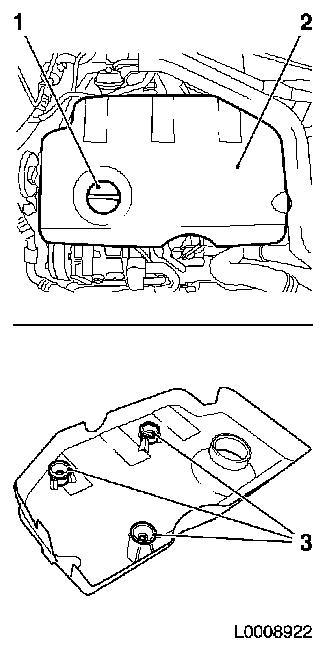
Remove engine cover (2)
| • |
Detach oil filler port closure cap (1)
|
| • |
Pull off engine cover
Note: Rubber retainers
(3) must remain on engine cover
|
| • |
Attach oil filler port closure cap
|
|
|
|
| 5. |
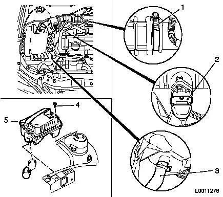
Remove air cleaner housing (5) with air intake hose
| • |
Disconnect wiring harness plug (2) from hot film mass air flow
meter
|
| • |
Detach air intake hose from air intake pipe
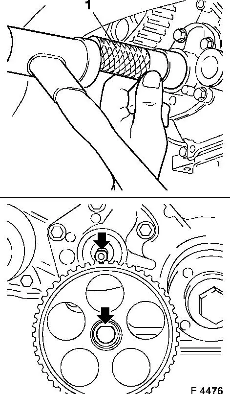
|
| • |
Detach air cleaner housing from wheel housing
|
| • |
Detach water drain hose (3) from air cleaner housing
|
|
|
|
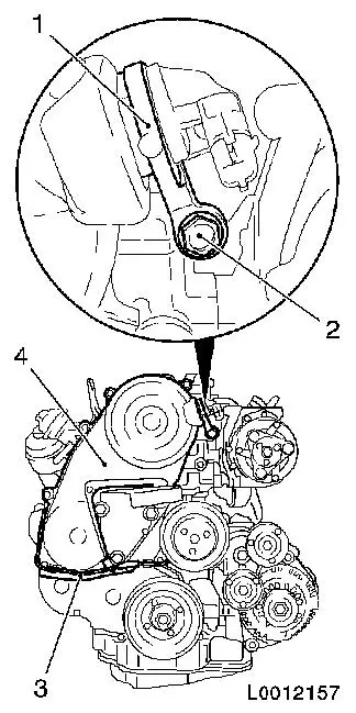
| 6. |
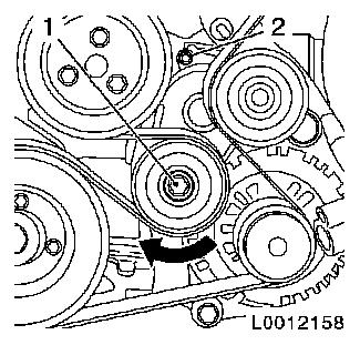
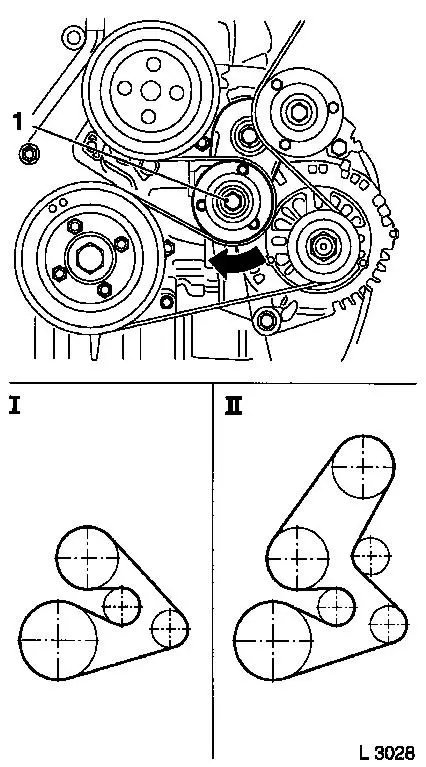
Remove ribbed V-belt
| • |
Mark direction of rotation
|
| • |
Apply tension to ribbed V-belt tensioner via bolt (1) in the
direction of the arrow
|
| • |
Fix ribbed V-belt tensioner to bore (2)
|
|
|
|
| 7. |
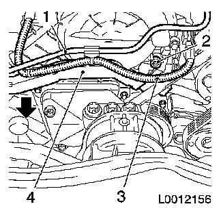
Detach wiring trough (4) from front toothed belt cover
(top)
| • |
Detach wiring harness (3)
| – |
Disconnect camshaft sensor wiring harness plug
|
|
| • |
Unclip wiring trough in direction of arrow
|
|
|
|
| 8. |
Detach front toothed belt cover (top) (4)
| • |
Unscrew 8x bolts
Note: Note different
bolt lengths
|
| • |
Remove camshaft sensor bracket (1)
|
|
|
|
| 9. |
Raise vehicle by its full height
|
| 10. |
Detach the lower engine cover and right engine splash guard
|
| 11. |
Place collecting basin underneath.
|
| 12. |
Drain engine oil
| • |
Unscrew oil drain bolt (3)
|
| • |
Tighten oil drain bolt 78.4 Nm
|
|
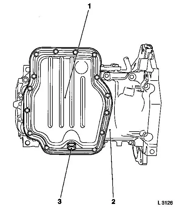
| 13. |
Detach lower part of oil pan (1) from upper part of oil pan (2)
with KM-J-37228
|
|
|
| 14. |
Remove front exhaust pipe
| • |
Detach from start-up catalytic converter
|
| • |
Detach from central silencer
|
|
|
|
| 15. |
Detach oil dipstick guide tube from upper part of oil pan
|
|
|
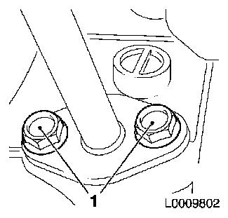
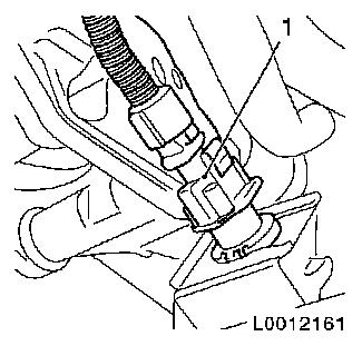
| 16. |
Disconnect engine oil level sensor wiring harness plug (1)
|
|
|
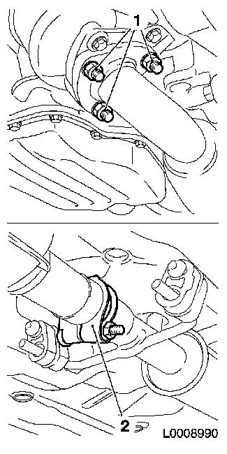
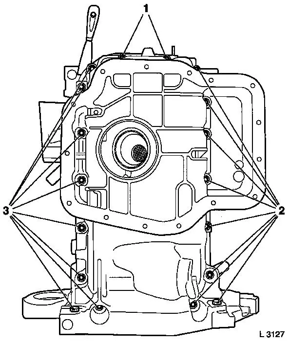
| 17. |
Detach upper part of oil pan from cylinder block
| • |
Unscrew bolt (2) and (3)
|
| • |
Separate upper part of oil pan from cylinder block with a broad
spatula
|
|
|
|
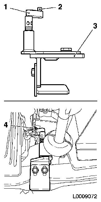
| 18. |
Insert KM-6173 (3)
| • |
Align support bearing (1)
|
| • |
Raise support bearing until journal (2) sits flush in mount
(4)
|
|
|
|
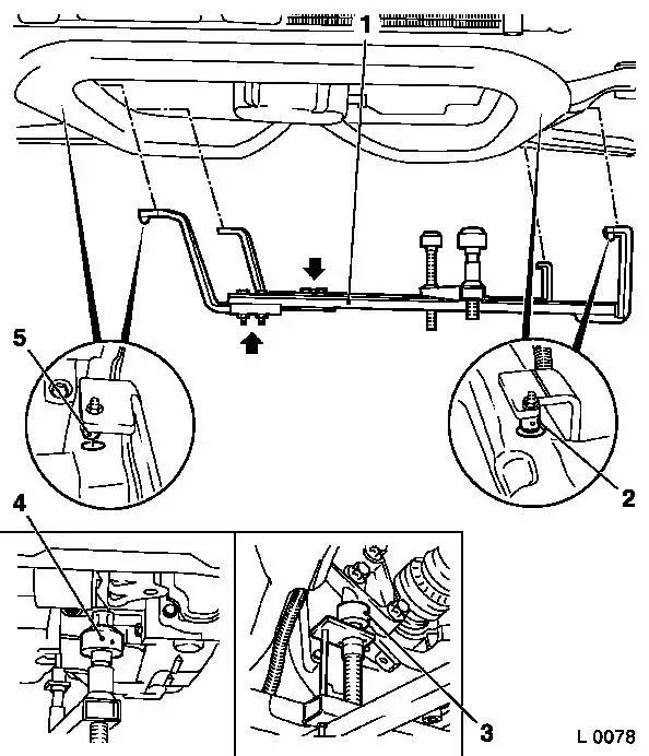
| 19. |
Attach KM-6001-A (1)
Note: Attaching
KM-6001-A guarantees perfect alignment of the drive unit with the
front axle body
| • |
Slacken 4x bolts (arrows) in adjusting rails
|
| • |
Insert KM-6001-A
| – |
Insert journals (2) and (5) in guide holes in front axle
body
|
|
| • |
Tighten 4x bolts in adjusting rails
|
| • |
Adjust support bearings, front (4) and rear (3)
| – |
Raise support bearings up to the stop on the guide journals
Note: The guide
journals must be seated free from play in the support bearings
|
|
|
|
|
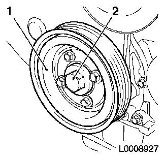
| 20. |
Detach torsional vibration damper (1)
| • |
Unscrew 4x bolts
Note: Counterhold at
bolt (2)
|
|
|
|
| 21. |
Lower vehicle by its full height
|
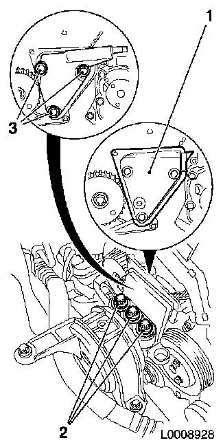
| 22. |
Remove engine damping block support
| • |
Detach from engine damping block bracket
|
| • |
Detach from cylinder block
|
| • |
Remove engine damping block adapter (1)
|
|
|
|
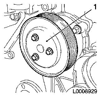
| 23. |
Remove coolant pump drive gear (1)
|
|
|
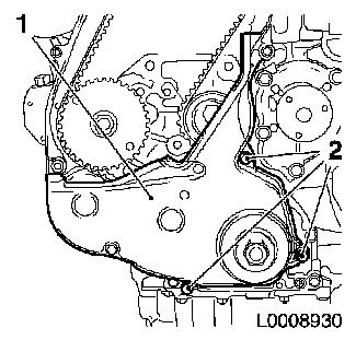
| 24. |
Remove front toothed belt cover (lower) (1)
|
|
|
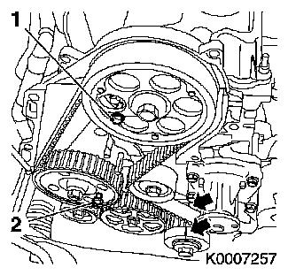
| 25. |
Move crankshaft in direction of engine rotation to "Cylinder
no.1 combustion stroke TDC"
Note: Marking on
toothed belt drive gear must align with projection on oil pump
cover (arrows)
| • |
Fix with TDC fixing bolt (M6) (1) camshaft drive gear
|
| • |
Fix with TDC fixing bolt (M8) (2) high pressure pump gear
|
|
|
|
| 26. |
Remove toothed belt
| • |
Mark direction of rotation
|
| • |
Slacken the toothed belt tension roller
|
| • |
Apply preliminary tension to toothed belt tension roller with
hexagon (2) in direction of arrow
|
| • |
Fix toothed belt tension roller in pre-tensioned position
|
|
|
|
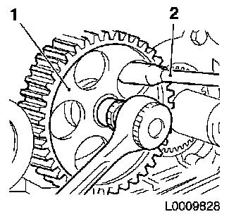
| 27. |
Remove oil pump gear (1)
| • |
Unscrew nut
Note: Counterhold with
socket wrench (2)
|
|
|
|
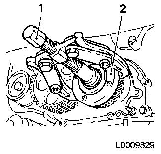
| 28. |
Remove toothed belt drive gear (2)
| • |
Unscrew bolt
Note: Counterhold with
KM-662-C
|
| • |
Remove toothed belt drive gear with KM-161-B (1)
|
|
|
|
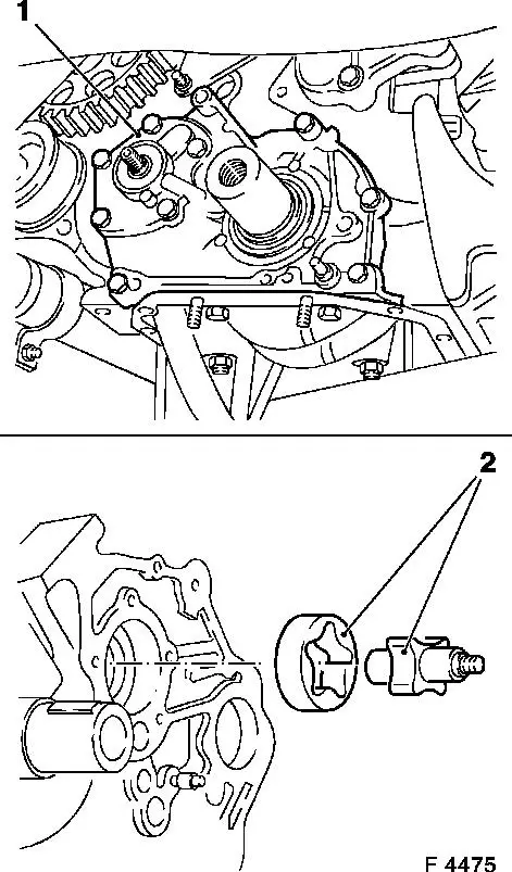
| 29. |
Remove oil pump cover (1)
| • |
Unscrew 9x bolts
Note: Note different
bolt lengths
|
| • |
Remove inner rotor and outer rotor (2)
|
|
|
|
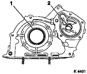
| 30. |
Remove crankshaft seal ring (1)
Important: Do not damage sealing
surfaces
|
| • |
Prise out seal ring with suitable tool
|
|
| 31. |
Remove oil pump seal ring (2)
Important: Do not damage sealing
surfaces
|
| • |
Prise out seal ring with suitable tool
|
|
|
|
 Install
| 32. |
Clean sealing surfaces.
|
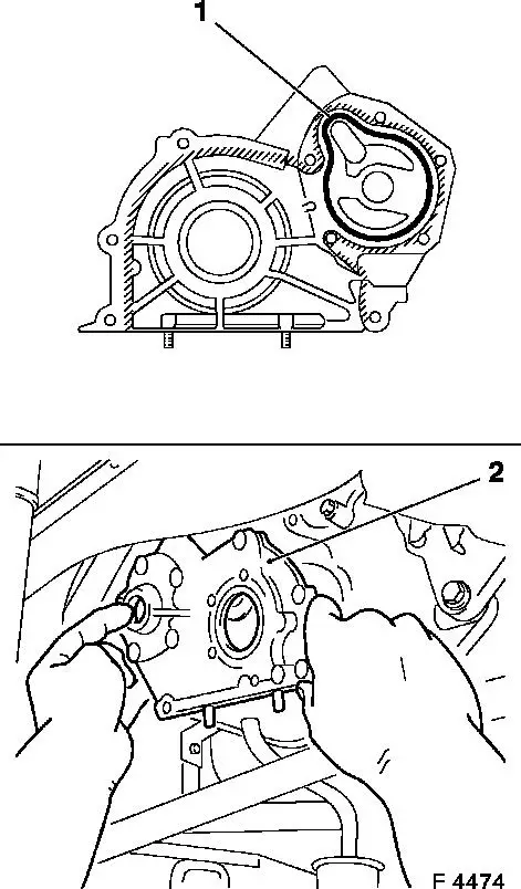
| 33. |
Install oil pump cover (2)
Important: Applying the adhesive
sealing compound (black) and the assembly of the oil pump cover
including the torque test must take place within 10 minutes
|
| • |
Apply a bead of adhesive sealing compound (black) to the
sealing surface (cross-hatching) of the oil pump cover
|
| • |
insert inner and outer rotor in cylinder block
|
| • |
Tighten 9x bolt 9.8 Nm
Note: Note different
bolt lengths
|
|
|
|
| 34. |
Install crankshaft seal ring
| • |
Drive in crankshaft seal ring with KM-656 (1) as far as the stop
|
|
|
|
| 35. |
Install oil pump seal ring
| • |
Insert new seal ring in oil pump cover
|
| • |
Drive in as far as the stop with KM-657 (1)
|
|
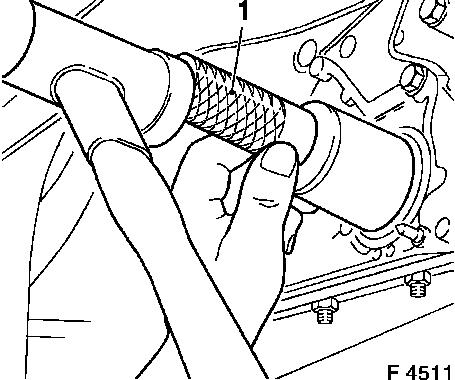
| 36. |
Fit oil pump drive gear
| • |
At oil pump
Note: Note installation
position (arrow)
|
| • |
Tighten nut 60 Nm , slacken nut
(wait 60 seconds), tighten nut 60 Nm
|
|
|
|
| 37. |
Install toothed belt drive gear
| • |
Attach toothed belt drive gear to crankshaft
Note: Note spring
washer
|
| • |
Tighten bolt 196 Nm
Note: Counterhold with
KM-662-C
|
|
| 38. |
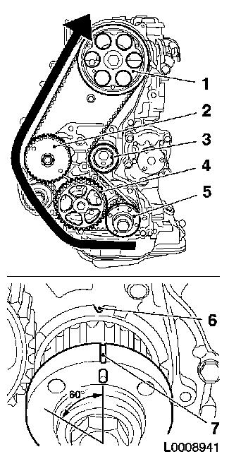
Install toothed belt
Note: TDC fixing bolts
must be installed in the high pressure drive gear and camshaft
drive gear and markings (6) and (7) must align
| • |
Position toothed belt
| – |
Toothed belt must be tensioned in the direction of the arrow
from the toothed belt drive gear (5) via the oil pump drive gear
(4) and high pressure pump drive gear (2) to the camshaft sprocket
(1)
|
| – |
Observe direction of rotation
|
|
| • |
Slacken the toothed belt tension roller (3)
|
| • |
Remove 2x TDC fixing bolt
|
| • |
Turn crankshaft 60° against the direction of engine
rotation
|
| • |
Tighten toothed belt tension roller 38.2 Nm
|
|
|
|
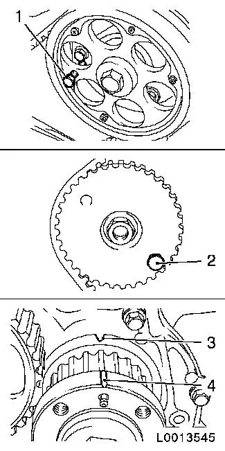
| 39. |
Timing, Check
| • |
Turn crankshaft 6 revolutions in direction of engine rotation
to the adjustment position
|
| • |
The following factors must be present at the adjustment
position
Note: If one of these
factors is not present, the timing must be adjusted
| 1. |
TDC fixing bolt M6 (1) must be able to be inserted
in the camshaft drive gear |
| 2. |
TDC fixing bolt M8 (2) must be able to be inserted
in the high pressure pump drive gear |
| 3. |
Marking (4) on the toothed belt drive gear must
align with the marking (3) on the oil pump housing cover |
|
| • |
Remove 2x TDC fixing bolt
|
|
|
|
| 40. |
Install front toothed belt cover (lower)
|
| 41. |
Install coolant pump drive gear
| • |
Tighten 3x bolt 12.3 Nm
|
|
| 42. |
Install engine damping block bracket
| • |
Insert engine damping block adapter
|
| • |
Attach engine damping block support to cylinder block
|
| • |
Engine damping block support to engine damping block
bracket
|
|
| 43. |
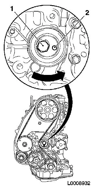
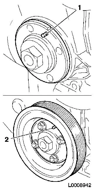
Raise vehicle by its full height
|
Important: Journal (1) of toothed
belt drive gear must engage in the bore (2) of the torsional
vibration damper
|
| 44. |
Install torsional vibration damper
| • |
Tighten 4x bolt 19.6 Nm
Note: Counterhold
against bolt, toothed belt drive gear
|
|
|
|
| 45. |
Remove engine mount KM-6173
|
| 46. |
Remove engine mount KM-6001-A
|
| 47. |
Install upper part of oil pan
| • |
Apply a bead of silicone sealant (grey) to the sealing surface
of the upper part of the oil pan
|
| • |
Tighten 18x bolt 9.8 Nm
|
|
| 48. |
Connect engine oil level wiring harness plug
|
| 49. |
Attach oil dipstick guide tube to upper part of oil pan
| • |
Tighten 2x bolts 9.8 Nm
|
|
| 50. |
Install front exhaust pipe
| • |
Attach to start-up catalytic converter
|
| • |
Attach to central silencer
|
|
| 51. |
Remove lower part of oil pan
| • |
Apply a bead of silicone sealant (grey) to the sealing surfaces
of the lower part of the oil pan
|
| • |
Tighten 15x bolt 9.8 Nm
|
|
| 52. |
Install lower engine cover and right engine splash guard
|
| 53. |
Lower vehicle by its full height
|
| 54. |
Install front toothed belt cover (top)
| • |
Tighten 8x bolt 9.8 Nm
Note: Note different
bolt lengths
|
| • |
Install camshaft sensor bracket
|
| • |
Attach vacuum line to toothed belt cover
|
|
| 55. |
Attach wiring trough to front toothed belt cover (top)
| • |
Attach wiring harness
| – |
Connect camshaft sensor wiring harness plug
|
|
|
| 56. |
Insert ribbed V-belt
Note: Note running
direction of ribbed V-belt
| • |
Position ribbed V-belt
| – |
I. Ribbed V-belt without air conditioning
|
| – |
II. Ribbed V-belt with air conditioning
|
|
| • |
Apply tension to ribbed V-belt tensioner via bolt (1) in the
direction of the arrow
|
| • |
Release ribbed V-belt tensioner
|
|
|
|
| 57. |
Install air cleaner housing with air intake hose
| • |
Attach water drain hose to air cleaner housing
|
| • |
Attach air intake hose to air intake pipe
|
| • |
Connect wiring harness plug to air mass flow meter
|
|
| 58. |
Top up engine oil, check oil level
|
| 59. |
Install engine cover
| • |
Detach oil filler port closure cap
|
| • |
Attach oil filler port closure cap
|
|
| 61. |
Connect battery
| • |
Attach earth connection to earth terminal
|
|
| 62. |
Program volatile memories
|
|
