|
Removing and installing both camshafts
 Remove Remove
| 2. |
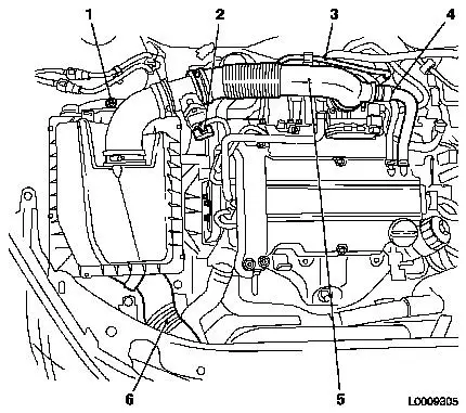
Remove air cleaner housing
| • |
Disconnect mass air flow sensor wiring harness plug (2)
|
| • |
Unclip tank vent line (3)
|
| • |
Detach engine vent hose (4) from air intake hose
|
| • |
Detach air intake hose (5) from throttle valve body
|
| • |
Detach air cleaner housing
| – |
Unclip rubber mounting at the bottom
|
| – |
Remove air intake pipe (6)
|
|
|
|
|
| 3. |
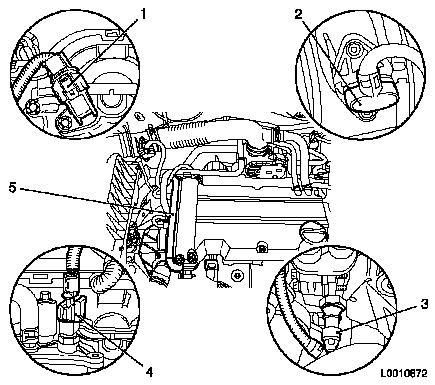
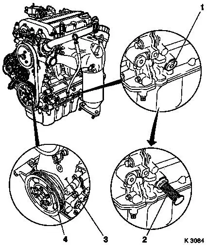
Disconnect wiring harness plugs for camshaft sensor (1), hot
film mass air flow meter (2), oil pressure switch (3) and coolant
temperature sensor (4)
|
| 4. |
Unclip wiring trough (5) from cylinder head cover
|
|
|
| 5. |
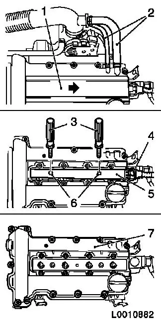
Remove engine vent hoses (2) from cylinder head cover
|
| 6. |
Remove ignition module
| • |
Disconnect cooling module wiring harness plug (4)
|
| • |
Pull the cover of the ignition module (1) away from the
cylinder head cover in the direction of the arrow
|
Important: Do not tilt
|
| • |
Remove ignition module (5) from spark plugs with KM-6009 (3)
|
|
| 7. |
Detach cylinder head cover (7) from cylinder head
|
|
|
| 8. |
Remove gasket remnants and clean sealing surfaces
|
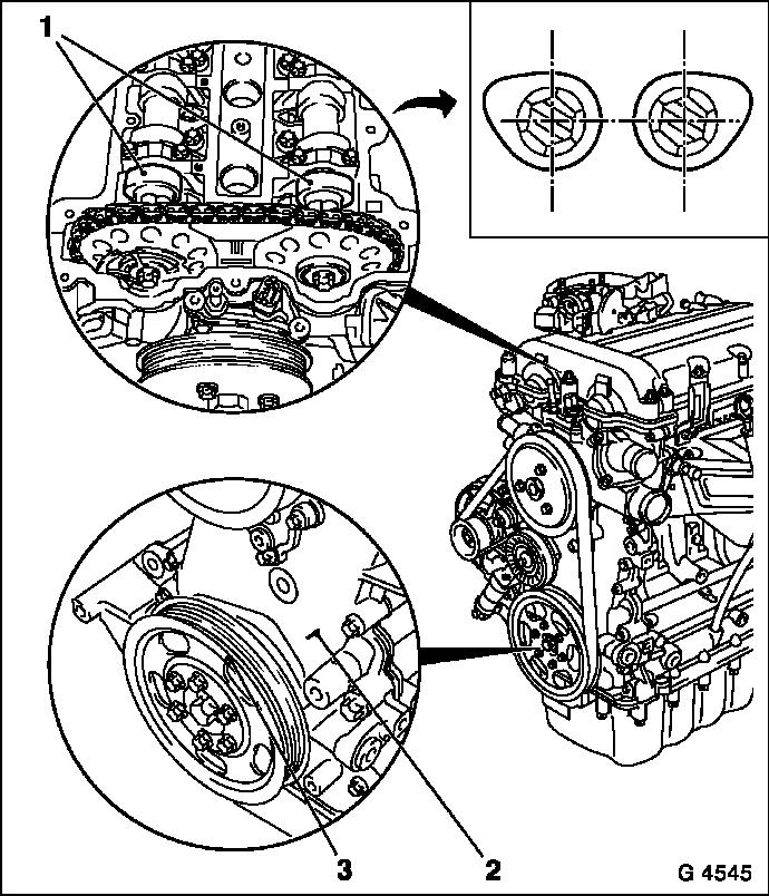
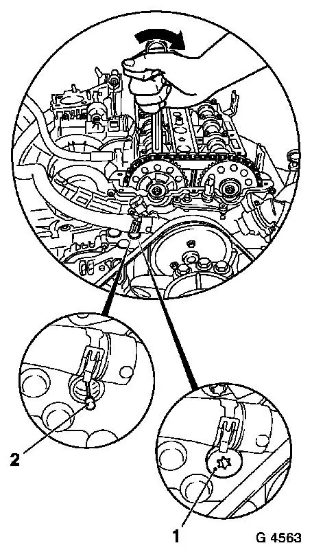
| 9. |
Move crankshaft in direction of engine rotation to just before
"cylinder 1 TDC of combustion stroke"
| • |
The marking (3) on the crankshaft belt pulley is just before
the cast projection (2) on the timing case
|
| • |
In this position, the cams (1) of cylinder 1 are at "TDC of
combustion stroke" (both cams point outwards)
|
|
|
|
| 10. |
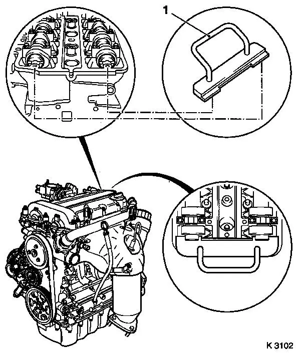
Remove closure bolt of chain tensioner (1) from timing case
|
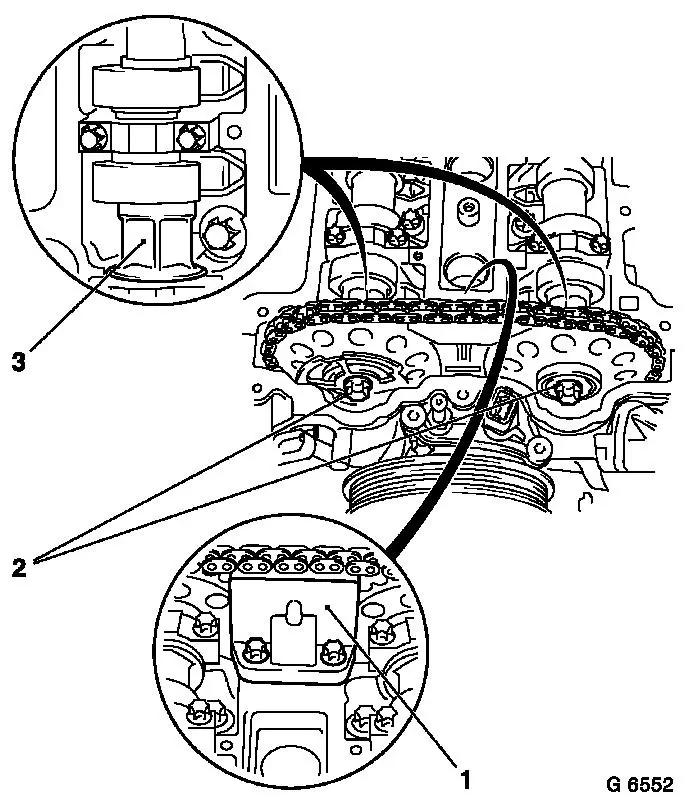
| 11. |
Lock chain tensioner with KM-955-1
(2)
| • |
Apply tension to intake camshaft in the direction of engine
rotation via hexagon (direction of arrow)
|
|
|
|
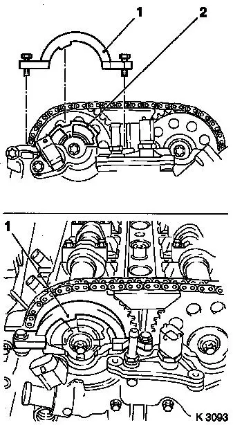
| 12. |
Detach sliding rail (1) from cylinder head
|
| 13. |
Remove camshaft sprockets
| • |
Unscrew 2x bolts (2)
| – |
Counterhold with open-ended wrench against the hexagon of the
camshafts (3)
|
|
| • |
Take out camshaft sprockets
|
|
|
|
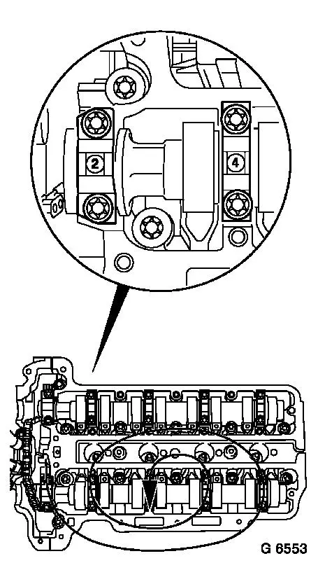
| 14. |
Note marking before dismantling camshaft bearing cap
|
Marking, exhaust camshaft
|
= 1 - 3 - 5 - 7 - 9
|
|
Marking, intake camshaft
|
= 2 - 4 - 6 - 8 - 10
|
|
| 15. |
Remove exhaust camshaft
Note: When releasing
the camshaft bearing caps, ensure that the camshaft is seated
evenly on the bearing seats
| • |
Slacken camshaft bearing caps in stages 1/2 to 1 turn
|
| • |
Take out camshaft bearing caps
| – |
Set aside in the correct order
|
|
| • |
Remove exhaust camshaft
|
|
| 16. |
Remove intake camshaft
Note: When releasing
the camshaft bearing caps, ensure that the camshaft is seated
evenly on the bearing seats
| • |
Slacken camshaft bearing caps in stages 1/2 to 1 turn
|
| • |
Take out camshaft bearing caps
| – |
Set aside in the correct order
|
|
|
|
|
 Install
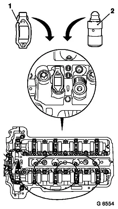
| 18. |
Check camshaft and camshaft bearing for wear
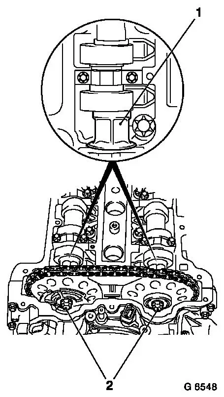
Note: If the camshaft
bearings are faulty, the cylinder head must be replaced. When
replacing the camshaft, the roller cam followers (1) and hydraulic
valve lifters (2) must be replaced
|
| 19. |
Install intake camshaft
| • |
Coat sliding surfaces with MoS2 lubricating paste
|
| • |
Insert intake camshaft
Note: Insert camshaft
in such a way that the cams of cylinder 1 are set at "TDC of
combustion stroke" (cams point outwards)
|
Important: Note mark and
allocation
|
| • |
Insert camshaft bearing caps
|
| • |
Install camshaft bearing cover
Note: Tighten camshaft
bearing caps in stages, working in a spiral from inside to
outside
|
|
| 20. |
Install exhaust camshaft
| • |
Coat sliding surfaces with MoS2 lubricating paste
|
| • |
Insert exhaust camshaft
Note: Insert camshaft
in such a way that the cams of cylinder 1 are set at "TDC of
combustion stroke" (cams point outwards)
|
Important: Note mark and
allocation
|
| • |
Insert camshaft bearing caps
|
| • |
Install camshaft bearing cover
Note: Tighten camshaft
bearing caps in stages, working in a spiral from inside to
outside
|
|
| 21. |
Tighten camshaft sprockets hand-tight with new bolts
| • |
Screw in 2x bolts
| – |
Tighten hand-tight
Note: It must still be
possible to turn the phase sensor disc on the intake camshaft by
hand
|
|
|
| 22. |
Attach sliding rail to cylinder head
|
|
|
| 23. |
Turn camshafts by the hexagon (short distance) until KM-953 (1) can be inserted in the grooves of
the camshafts
Note: Turn camshafts
carefully and evenly
| • |
KM-953 must engage as far as the stop
in the grooves of the camshafts
|
|
|
|
| 24. |
Turn phase sensor disc (2) in such a way that KM-954 (1) can be inserted on the timing case
|
|
|
| 25. |
Attach KM-954 to timing case
|
| 26. |
Take KM-955-1 out of chain
tensioner
|
| 27. |
Unscrew closure bolt, crankshaft bearing bridge (1)
|
| 28. |
Adjust TDC of combustion stroke of cylinder 1
| • |
Insert KM-952 (2)
| – |
Turn crankshaft evenly until KM-952
engages
|
| – |
Marking on the crankshaft belt pulley (4) must align with the
cast projection (3) on the timing case
|
|
|
|
|
| 29. |
Remove locking pin of chain tensioner KM-955-1
| • |
Tighten chain tensioner closure bolt 50
Nm
|
|
| 30. |
Fasten camshaft sprockets
Note: Tightening torque
10 Nm serves to fix the camshaft
sprockets and the phase sensor disc temporarily
| • |
Tighten 2x bolt (2) 10 Nm
Note: First of all
tighten bolt of intake camshaft sprocket
| – |
Counterhold the camshafts on the hexagon (1)
|
|
|
|
|
| 31. |
Remove locking tools KM-954 , KM-953 and KM-952
Note: Locking tools may
not be used for counterholding
|
| 32. |
Tighten camshaft sprockets
Note: Use a second
person
| • |
Tighten 2x bolt 50 Nm + 60°
|
|
| 33. |
Timing, Check
| • |
Turn crankshaft through 720°
|
| • |
Insert KM-953 into camshafts
|
| • |
Attach KM-954 on phase sensor
disc
Note: if KM-954 cannot be inserted, the operation "Timing,
Adjust" must be repeated
|
|
| 34. |
Remove KM-954 , KM-953 and KM-952
|
| 35. |
Attach cylinder head cover (1)
Important: Complete assembly work
within 10 minutes
|
| • |
Apply a bead of silicone sealing compound (dimension I) approx.
2 mm thick to the dividing joints of the cylinder head and timing
case
|
Important: Bolts must be checked
visually to check whether the elastomer seal is damaged. If the
elastomer seal is damaged, the bolt must be replaced with a new
one.
|
| • |
Tighten 13x bolt 8 Nm
|
|
|

|
| 36. |
Install ignition module
| • |
Connect ignition module to spark plugs
|
| • |
Attach ignition module cover to cylinder head cover
|
| • |
Connect ignition module wiring harness plug
|
|
| 37. |
Clip wiring trough to cylinder head cover
|
| 38. |
Connect wiring harness plugs for camshaft sensor, hot film mass
air flow meter, oil pressure switch and coolant temperature
sensor
|
| 39. |
Install air cleaner housing
| • |
Connect air intake hose
|
| • |
Attach engine vent hose
|
| • |
Connect 2x wiring harness plugs
| – |
Hot film air mass flow meter, tank vent valve
|
|
|
|
