|
Replace intake manifold
 Remove Remove
| 1. |
Disconnect ground cable from battery
|
| 2. |
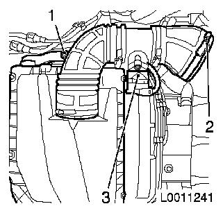
Remove air filter housing with mass air flow meter
| • |
Detach mass air flow meter wiring harness plug (3)
|
| • |
Detach air intake hose from air intake pipe
|
|
|
|
| 3. |
Remove air intake manifold
|
| 4. |
Remove engine vent hose from cylinder head cover
|
| 5. |
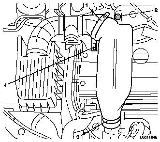
Detach air intake pipe from air intake hose
|
| 6. |
Detach air intake pipe from turbocharger
| • |
Release clamp (3)
Note: Seal air intake
pipe at turbocharger
|
|
| 7. |
Remove air intake pipe
|
|
|
| 8. |
Remove charge air hose (2)
|
|
|
| 9. |
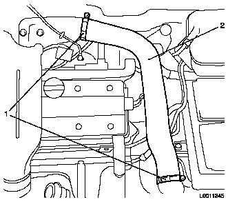
Detach charge air deflection pipe
| • |
Unclip vacuum line from bracket (2)
|
| • |
Remove charge air deflection pipe
|
|
|

|
| 10. |
Open coolant drain bolt
|
| 12. |
Close coolant drain screw
|
| 13. |
Detach tank vent valve from intake manifold
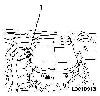
|
| 14. |
Detach throttle body coolant lines (2) from throttle body
|
| 15. |
Disconnect throttle body wiring harness plug (1)
|
|
|
Important: Damaged valve
connections may lead to vehicle fires as a result of leaks.
|
| 16. |
Detach tank vent valve hose from throttle body. Disconnect
wiring harness plug from tank vent valve
Note: Take care not to
damage the valve connecting piece when detaching the tank vent
valve hose. Damaged valves must be replaced.
|
| 17. |
Mark direction of travel of ribbed V-belt.
|
| 18. |
Tension ribbed V-belt tensioner in direction of arrow
|
|

|
| 20. |
Unclip wiring harness plug for crankshaft pulse pick-up (1)
from bracket
|
|
|
| 21. |
Loosen lower alternator mounting bolt (3).
|
| 22. |
Detach alternator shackle (2) from intake manifold, coolant
flange and alternator.
|
| 23. |
Detach alternator support (1) from intake manifold and
alternator
Note: Swivel alternator
to rear
|
|
|
| 24. |
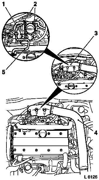
Detach brake servo vacuum line (1) from intake manifold
|
| 25. |
Release fuel pressure using pressure tester KM-J-34730-9 via test connection -.
Note: Collect exiting
fuel in a suitable container - observe safety regulations and
national legislation
|
| 26. |
Remove fuel lines (2) and (3) from fuel rail and fuel pressure
regulator
|
| 27. |
Detach vacuum lines (4) and (5) from fuel pressure regulator
and intake manifold
|
|
|
| 28. |
Detach plug strip (3) from injectors and place to one side
|
| 29. |
Detach ground strap (2) from intake manifold
|
| 30. |
Detach vacuum reservoir bracket (1) from intake manifold
|
| 31. |
Detach intake manifold from cylinder head and remove
|
|
|
| 32. |
Clean sealing surfaces and remove gasket remnants.
|
 Install
| 33. |
When replacing: transfer attaching parts
|
| 34. |
Attach intake manifold to cylinder head 22 Nm
| • |
Use new gasket and fastening nuts
|
|
| 35. |
Attach vacuum reservoir bracket to intake manifold 25 Nm
|
| 36. |
Attach ground strap to intake manifold
|
| 37. |
Attach plug strip to injectors
Note: Pay attention to
correct fitting - plug strip must audibly engage
|
| 38. |
Attach vacuum line to fuel pressure regulator and intake
manifold
|
| 39. |
Attach fuel lines to fuel rail and fuel pressure regulator
15 Nm
|
| 40. |
Attach brake servo vacuum line to intake manifold
|
| 41. |
Attach alternator shackle to alternator, coolant flange and
intake manifold 20 Nm
|
| 42. |
Attach alternator support to alternator and intake manifold
20 Nm
|
| 43. |
Fasten alternator to alternator support (lower fastening bolt)
35 Nm
|
| 44. |
Position ribbed V-belt
| • |
Ensure running direction and installation position of ribbed
V-belt is correct
|
|
| 45. |
Tension ribbed V-belt using ribbed V-belt tensioner
|
| 46. |
Clip crankshaft sensor wiring harness plug into bracket.
|
| 47. |
Attach tank vent valve hose to throttle body
|
| 48. |
Connect tank vent valve wiring harness plug to tank vent
valve
|
| 49. |
Attach throttle body coolant lines to throttle body
|
| 50. |
Attach engine vent hose to cylinder head cover
|
| 51. |
Attach charge air hose to intercooler 3.5 Nm
|
| 52. |
Attach charge air deflection pipe to intake manifold 9 Nm
|
| 53. |
Install air cleaner housing with mass air flow meter
| • |
Insert air cleaner housing
|
| • |
Attach air intake hose to air intake pipe
|
| • |
Connect mass air flow meter wiring harness plug
|
|
| 54. |
Attach tank vent valve to air cleaner housing.
|
| 55. |
Attach engine vent hose to cylinder head cover
|
| 56. |
Attach air intake pipe to air intake hose and turbocharger
3.5 Nm
|
| 57. |
Attach bulkhead cover plate insulation 4 Nm .
|
| 58. |
Connect ground cable to battery.
|
| 59. |
Always use antifreeze 19 40 650 / 9194431 (red) and ensure that
the concentration is 50% water and 50% antifreeze. The antifreeze
does not just protect the entire cooling system from freezing, but
also protects all coolant-flushed parts from rust-corrosion/calcium
deposits. It is therefore important to add antifreeze, even in
tropical countries.
|
| 60. |
The water quality also plays an important role in addition to
the mix ratio. Water of drinkable quality usually meets these
requirements. The quality of purified sea water is inadequate!
|
| 61. |
Damage may also be caused to the engine if unauthorised
anti-freeze agent is used!
|
| 62. |
If radiator, cylinder head or cylinder head gasket have been
replaced the old coolant must not be re-used.
|
Important: Vehicles with air
conditioning: switch air conditioning off and set to ECO mode with
ECC
|
| 63. |
Open cooling system
Warning: Cooling system is under
pressure
|
| • |
Unscrew coolant expansion tank cover
|
|
| 64. |
Fill with coolant up to lower venting line (1) at coolant
expansion tank
|
| 65. |
Seal off cooling system
| • |
Screw in coolant expansion tank cover
|
|
| 66. |
Start engine and allow to warm up
| • |
Allow engine to warm up at idling speed of up to 2500 rpm until
first radiator fan setting switches on
|
|
| 67. |
Vent cooling system
| • |
Allow engine to run for approximately 2 minutes at 2000 to 2500
rpm
Note: The air in the
cooling system is removed via the venting lines
|
|
| 68. |
Switch engine off and allow to cool
|
| 69. |
Check coolant level and also top up coolant to "COLD" mark
|
|
|
|
