|
Multi-plate clutch C1 and C2, Dismantle and
Assemble (AF22)
 Remove Remove
Important: Secure converter so it
does not fall out
|
| 1. |
Remove transmission
|
| 2. |
Attach transmission to KM-694-A
(2)
| • |
Attach assembly to KM-113-2 (1)
|
|
| 3. |
Remove oil drain bolt (3)
| • |
Drain transmission fluid and collect for damage diagnosis 
|
|
|
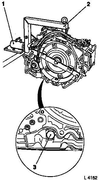
|
| 6. |
Remove drive shaft assembly with multi-plate clutch C1 and C2
|
|
| 7. |
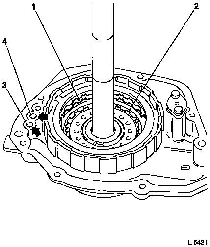
Check multi-plate clutch C1 piston (1)
Note: Ensure that the
piston can move correctly.
| • |
Fit drive shaft to rear housing cover
Note: Seal rings must
still be fitted to rear cover and to rear of drive shaft.
|
| • |
Cut off the end of KM-994 and insert
KM-994 in hole
|
| • |
Blow in air at low pressure (4 bar) (arrow 3)
|
|
| 8. |
Check multi-plate clutch C1 piston (2)
Note: Ensure that the
piston can move correctly.
| • |
Fit drive shaft to rear housing cover.
Note: Seal rings must
still be fitted to rear cover and to rear of drive shaft.
|
| • |
Cut off the end of KM-994 and insert
KM-994 in hole
|
| • |
Blow in air at low pressure (4 bar) (arrow 4)
|
|
|
|
| 9. |
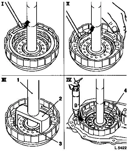
Dismantle multi-plate clutch C1 (I)
| • |
Prise off retainer with screwdriver
|
| • |
Remove flange, liner plates and steel plates
|
|
| 10. |
Dismantle multi-plate clutch C2 (II)
| • |
Prise off retainer with screwdriver
|
| • |
Remove flange, liner plates and steel plates
|
|
| 11. |
Remove return spring assembly (III)
| • |
Place KM-698 (2) using KM-514 (1) and KM-697 or
KM-311-1 on spring seat and compress
under a press
|
| • |
Undo retainer (3) using KM-396
|
|
| 12. |
Remove piston (4) for multi-plate clutch C2 (IV)
| • |
Fit drive shaft assembly to rear housing cover
|
| • |
Blow in air at low pressure (4 bar) (arrow) and remove
piston
Note: Assist with
pliers if necessary
|
|
|
| 13. |
Remove piston (1) for multi-plate clutch C1
| • |
Fit drive shaft assembly to rear housing cover
|
| • |
Cut off the end of KM-994 and insert
KM-994 in hole
|
| • |
Blow in air at low pressure (4 bar) (arrow)
|
| • |
Remove piston
Note: Assist with
pliers if necessary
|
|
| 14. |
Check sliding surfaces of liner plates and steel plates for
damage and wear, replace if necessary
Note: Place new liner
plates in transmission fluid for at least 2 hours before
installation
|
| 15. |
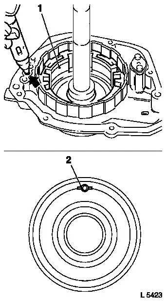
Check lock ball (2) of piston for multi-plate clutch C2
| • |
Check by shaking whether the lock ball can move
|
| • |
Check with air at low pressure whether the valve is sealed
|
|
|
|
 Install
|
| 16. |
Insert piston (2) for multi-plate clutch C1 in drive shaft
| • |
Insert piston (1) for multi-plate clutch C2 in drive shaft
|
| • |
Place return spring assembly (3) with friction washer (4) on
piston C1
|
| • |
Compress return spring assembly using KM-698 and KM-514 , KM-697 or KM-311-1
under a press
|
| • |
Insert new retainer using KM-396
|
|
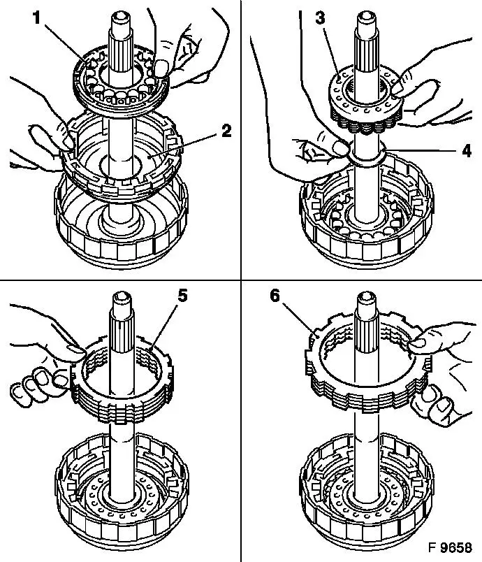
| 17. |
Place steel plate (first), liner plate and flange (5) last on
piston C2, alternating
Note: Surface with
rounded edge faces liner plate.
| • |
Insert retainer with screwdriver
|
|
| 18. |
Place steel plate (first), liner plate and flange (6) last on
piston C1, alternating
Note: Surface with
rounded edge faces liner plate.
| • |
Insert retainer with screwdriver
|
|
|
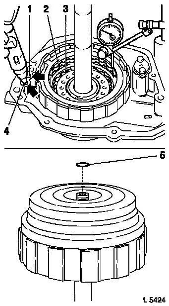
| 19. |
Measure piston stroke of multi-plate clutch C1
Note: If necessary,
correct necessary piston stroke by installing a suitable
compensating flange from the "Service" Department.
| • |
Fit drive shaft in rear cover
|
| • |
Cut off the end of KM-994 and insert
KM-994 in hole
|
| • |
Blow compressed air into hole in rear cover (4 bar) (arrow
4)
|
| • |
Place the dial gauge button on the top liner plate (3)
Note: Measured value:
1.52 to 1.89 mm
|
|
| 20. |
Measure piston stroke of multi-plate clutch C2
| • |
Fit drive shaft in rear cover
|
| • |
Cut off the end of KM-994 and insert
KM-994 in hole
|
| • |
Blow compressed air into hole in rear cover (4 bar) (arrow
1)
|
| • |
Place the dial gauge button on flange of multi-plate clutch C2
(2)
Note: Measured value:
1.52 to 1.89 mm
|
|
Important: Note O-ring (5).
|
| 21. |
Install drive shaft assembly with multi-plate clutch C1 and C2
|
|
|
Important: Secure converter so it
does not fall out
|
| 23. |
Install converter
|
| 24. |
Attach oil drain bolt (3) to transmission with seal ring
Note: Use new seal
ring.
| • |
Tighten oil drain bolt 40 Nm
|
|
| 25. |
Detach transmission assembly with KM-694-A from KM-113-2
(1)
| • |
Detach transmission from KM-694-A
(2)
|
|
| 26. |
Install transmission
| • |
Top up with transmission fluid
|
|
| 27. |
Check and correct transmission fluid level
|
|
|
|
