|
Remove and install gearshift module (F13 MTA)
Note: External
current reaching the gearshift module can cause damage. To
guarantee correct findings, a dismantled gearshift module should
not be reassembled.
 Remove Remove
| 1. |
Put transmission into neutral
| • |
Depress footbrake and move selector lever to "N" position
|
|
| 2. |
Remove battery support
|
| 3. |
Remove bracket for hydraulic modulator 
|
|
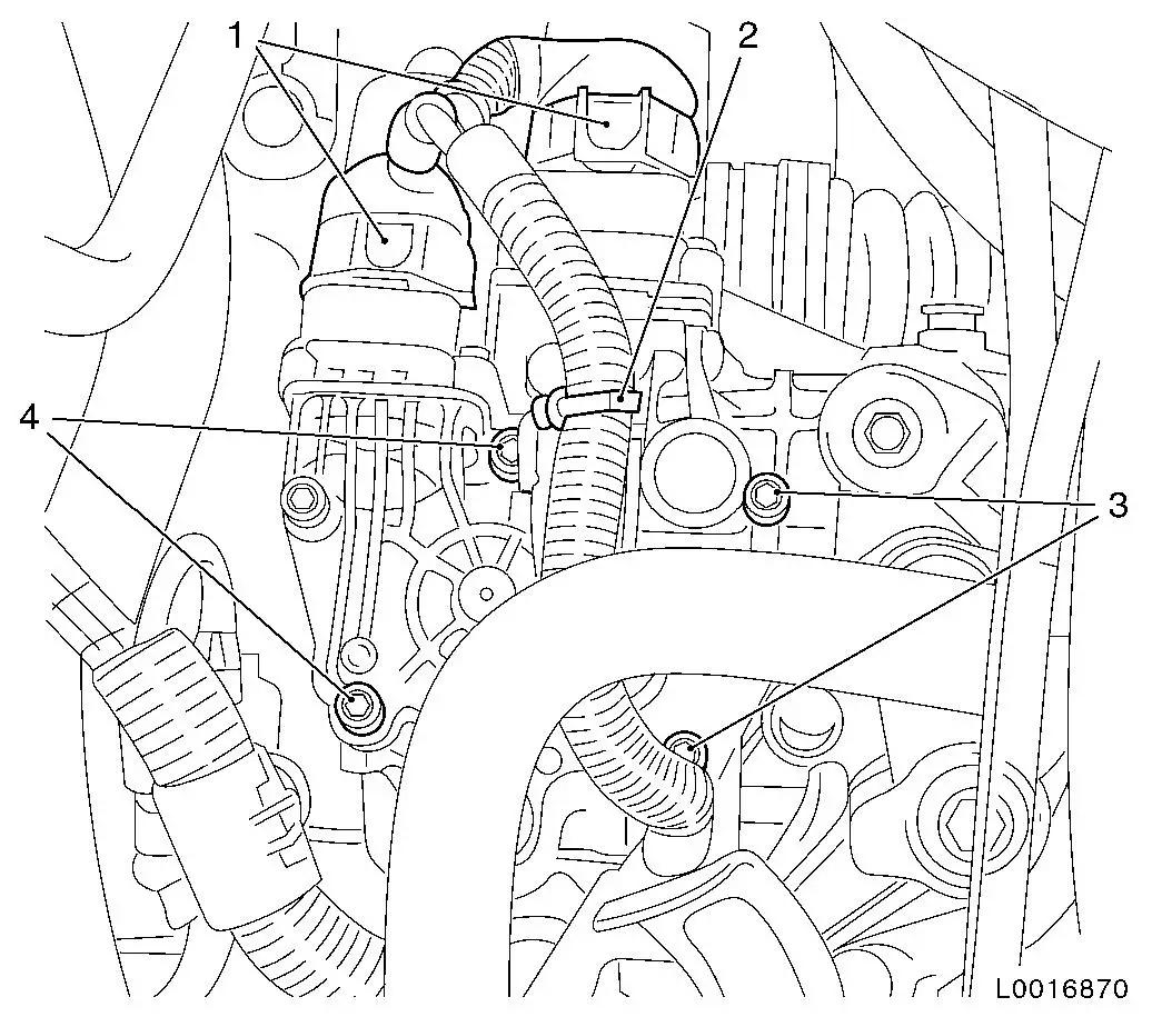
| 4. |
Disconnect 2x wiring harness plug (1) from gearshift module
|
| 5. |
Remove gearshift module
| • |
Unscrew 4x bolt (3) and (4)
|
| • |
Lift gearshift module, tilt forwards and remove
|
|
|
|
Important: If removal in this way
is not possible, e.g. if there is a fault, the selector motor and
gearshift motor must be removed individually. A dismantled
gearshift module may not be used again and must be replaced.
|
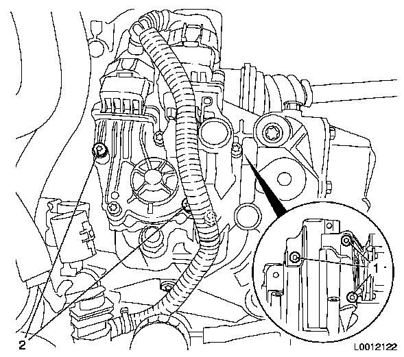
| 6. |
Remove selector motor and gearshift motor individually
Note: Only for
defective gearshift module.
| • |
Remove selector motor
| – |
Unscrew 3x bolt (1) and remove selector motor
|
|
| • |
Remove gearshift motor
| – |
Unscrew 2x bolt (2) and remove gearshift motor
|
|
|
|
|
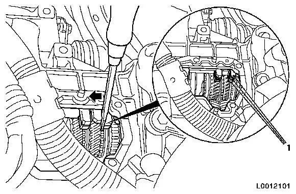
| 7. |
Put transmission into neutral
Note: Only necessary
for defective gearshift module.
| • |
Move shift forks to neutral position with a screwdriver
Note: All 3 shift forks
(1) must align and reverse gear may not be engaged.
|
|
|
| 8. |
Clean sealing surfaces
| • |
Clean sealing surface and threaded bores for gearshift
module
|
|
 Install
Important: The following work
step is only to be carried out up to gearshift module production
level G4D4 001 05 b. Production level is indicated by a sticker on
the gearshift module housing. From production level G4D4 001 05 c,
there is no impact marking on the toothed head of the gearshift
motor's pinion. For production levels with impact marking (e.g.
G4D4 001 03 e), the marks must align. Otherwise, fault memory
entries and system failure can be expected.
|
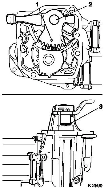
| 9. |
Move gearshift module to neutral position
| • |
Align the marking (1) on the gearshift lever shaft (2) with the
toothed head of the pinion, gearshift motor
|
| • |
Move gearshift lever shaft to the idling position
Note: Groove (3) is
visible and ends flush with the collared bush (removal or
as-delivered condition).
|
|
|
|
|
| 10. |
Install gearshift module
| • |
Insert gearshift module with new seal
|
| • |
Tighten 4x bolt (3) and (4) 11
Nm
Note: Use new
bolts.
|
| • |
Connect 2x wiring harness plug (1)
Note: Wiring harness
plug - black (gearshift motor), wiring harness plug - grey
(selector motor).
|
|
|
| 11. |
Install bracket for hydraulic modulator
| • |
Install hydraulic modulator
|
|
| 12. |
Install battery support
|
| 13. |
Program volatile memories
|
| 14. |
Set transmission parameters
|
| 15. |
Comply with the start-up routines required
|
|
