Engine Control Module Wiring Harness Replacement (1.4L
LDD)
Removal Procedure
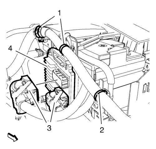
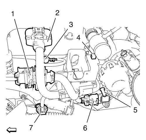
| 2. |
Disconnect the 2 engine
control module wiring harness plugs (3) from the engine control
module (4). |
| 3. |
Unclip the 3 wiring harness
clips (1, 2) from the engine control module wiring harness
brackets. |
| 4. |
Remove the engine control
module bracket along with the engine control module in top
direction from the battery tray. |
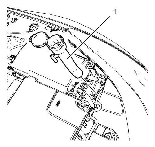
| 6. |
Remove the windshield washer
solvent container filler tube (1). |
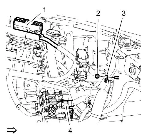
| 8. |
Remove the wiring harness
ground cable nut (2) and remove the wiring harness ground cable
(3). |
| 9. |
Remove the wiring harness plug
(1) in top direction. |
| 10. |
Disconnect the wiring harness
connection adapter plug (4). |
| 11. |
Unclip the wiring harness clip
from the drivetrain and front suspension frame front inner
support. |
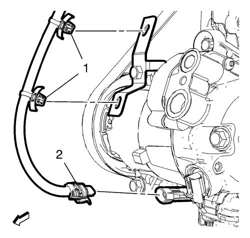
| 12. |
Unclip the wiring harness clip
(2) from the transmission bracket. |
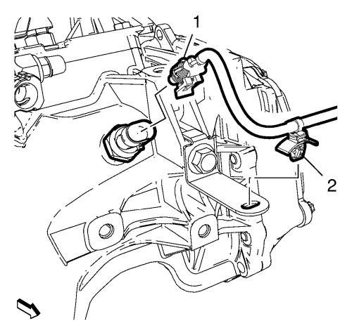
| 13. |
Disconnect the backup lamp
switch wiring harness plug (1). |
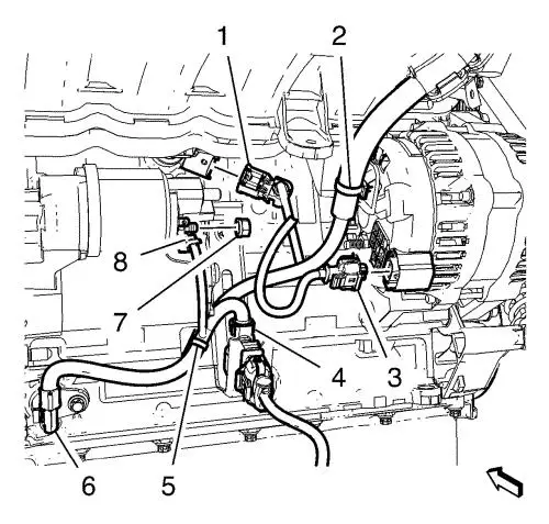
| 14. |
Unclip the heated oxygen
sensor wiring harness plug (1) from the retainer clip. |
| 15. |
Disconnect the engine coolant
temperature sensor wiring harness plug (7). |
| 16. |
Disconnect the ignition coil
module wiring harness plug (2). |
| 17. |
Disconnect the manifold
absolute pressure sensor wiring harness plug (6). |
| 18. |
Remove the ground cable bolt
(3) and the ground cable from the cylinder head. |
| 19. |
Disconnect the engine control
module wiring harness from the retainer clip (4). |
| 20. |
Unclip the engine control
module wiring harness from the engine control module wiring harness
bracket. Hang the engine control module wiring harness
aside. |
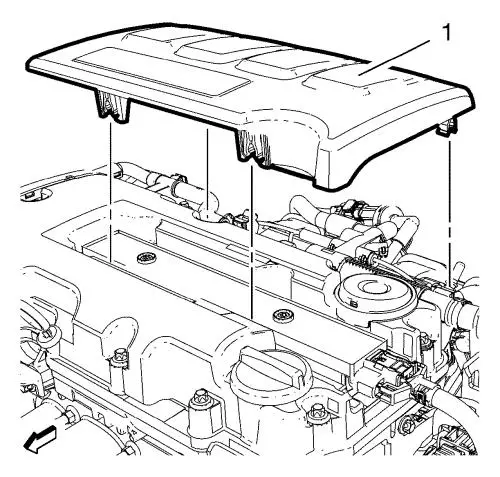
| 21. |
Unclip the engine emblem (1)
from the camshaft cover. |
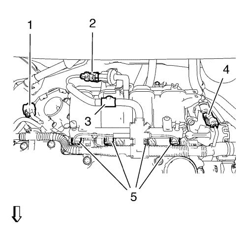
| 22. |
Disconnect the throttle body
wiring harness plug (1). |
| 23. |
Disconnect the evaporative
emission canister purge solenoid valve wiring harness plug
(2). |
| 24. |
Disconnect the intake manifold
runner solenoid valve wiring harness plug (4). |
| 25. |
Unclip the engine control
module wiring harness from the intake manifold (3). |
| 26. |
Disconnect the 4 fuel injector
wiring harness plugs (5). |
| 27. |
Disconnect the mass air flow
sensor wiring harness plug. |
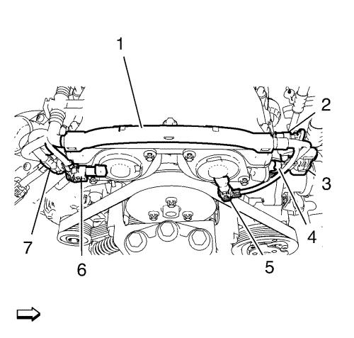
| 28. |
Disconnect the intake camshaft
position sensor wiring harness plug (7). |
| 29. |
Disconnect the intake camshaft
position actuator solenoid valve wiring harness plug (6).
|
| 30. |
Disconnect the exhaust
camshaft position sensor wiring harness plug (4). |
| 31. |
Disconnect the exhaust
camshaft position actuator solenoid valve wiring harness plug
(5). |
| 32. |
Disconnect the engine coolant
temperature sensor wiring harness plug (3). |
| 33. |
Disconnect the engine oil
pressure indicator switch wiring harness plug (2). |
| 34. |
Unclip the engine control
module wiring harness (1) in top direction from the camshaft
cover. |
| 36. |
Unclip the 2 wiring harness
clips (1) from the air conditioning compressor. |
| 37. |
Disconnect the air
conditioning compressor wiring harness plug (2). |
| 38. |
Disconnect the heated oxygen
sensor wiring harness plug (4). |
| 39. |
Disconnect the crankshaft
position sensor wiring harness plug (6) and unclip the wiring
harness clip (5) from the wiring harness bracket. |
| 40. |
Disconnect the generator
wiring harness plug (3). |
| 41. |
Disconnect the knock sensor
wiring harness plug (1). |
| 42. |
Remove the starter wiring
harness nut (7) and the starter wiring harness cable (8).
|
| 43. |
Unclip the wiring harness from
the generator bracket (2). |
| 45. |
Remove the engine wiring
harness from the vehicle. |
Installation Procedure
| 1. |
Position the engine wiring
harness to the vehicle. |
| 3. |
Clip in the wiring harness to
the generator bracket (2). |
| 4. |
Install the starter wiring
harness cable (8) and the starter wiring harness cable nut (7) and
hand tighten. |
| 5. |
Connect the knock sensor
wiring harness plug (1). |
| 6. |
Connect the generator wiring
harness plug (3). |
| 7. |
Connect the crankshaft
position sensor wiring harness plug (6) and clip in the wiring
harness clip (5) to the wiring harness bracket. |
| 8. |
Connect the heated oxygen
sensor wiring harness plug (4). |
| 9. |
Connect the air conditioning
compressor wiring harness plug (2). |
| 10. |
Clip in the 2 wiring harness
clips (1) to the air conditioning compressor. |
| 12. |
Clip in the engine control
module wiring harness (1) to the camshaft cover. |
| 13. |
Connect the engine oil
pressure indicator switch wiring harness plug (2). |
| 14. |
Connect the engine coolant
temperature sensor wiring harness plug (3). |
| 15. |
Connect the exhaust camshaft
position actuator solenoid valve wiring harness plug (5).
|
| 16. |
Connect the exhaust camshaft
position sensor wiring harness plug (4). |
| 17. |
Connect the intake camshaft
position actuator solenoid valve wiring harness plug (6).
|
| 18. |
Connect the intake camshaft
position sensor wiring harness plug (7). |
| 19. |
Connect the mass air flow
sensor. |
| 20. |
Connect the 4 fuel injector
wiring harness plugs (5). |
| 21. |
Clip in the engine control
module wiring harness to the intake manifold (3). |
| 22. |
Connect the intake manifold
runner solenoid valve wiring harness plug (4). |
| 23. |
Connect the evaporative
emission canister purge solenoid valve wiring harness plug
(2). |
| 24. |
Connect the throttle body
wiring harness plug (1). |
| 25. |
Clip in the engine emblem (1)
to the camshaft cover. |
| 26. |
Clip the engine control module
wiring harness to the engine control module wiring harness
bracket. |
| 27. |
Connect the engine control
module wiring harness to the retainer clip (4). |
| 28. |
Install the ground cable and
the ground cable bolt (3) to the cylinder head. Tighten to
8 N·m (71 lb in) . |
| 29. |
Connect the manifold absolute
pressure sensor wiring harness plug (6). |
| 30. |
Connect the ignition coil
module wiring harness plug (2). |
| 31. |
Connect the engine coolant
temperature sensor wiring harness plug (7). |
| 32. |
Clip in the heated oxygen
sensor wiring harness plug (1) to the retainer clip. |
| 33. |
Connect the backup lamp switch
wiring harness plug (1). |
| 34. |
Clip in the wiring harness
clip (2) to the transmission bracket. |
| 35. |
Clip in the wiring harness
clip to the drivetrain and front suspension frame front inner
support. |
| 36. |
Connect the wiring harness
connection adapter plug (4). |
| 37. |
Install the wiring harness
plug (1). |
| 38. |
Install the wiring harness
ground cable (3) and install the wiring harness ground cable nut
(2). |
| 40. |
Install the windshield washer
solvent container filler tube (1). |
| 42. |
Install the engine control
module bracket along with the engine control module to the battery
tray. |
| 43. |
Connect the 2 engine control
module wiring harness plugs (3) to the engine control module
(4). |
| 44. |
Clip in the 3 wiring harness
clips (1, 2) to the engine control module wiring harness
brackets. |
|
