Engine Control Module Wiring Harness Replacement (1.6 LDE, LXV,
1.8L 2H0)
Removal Procedure
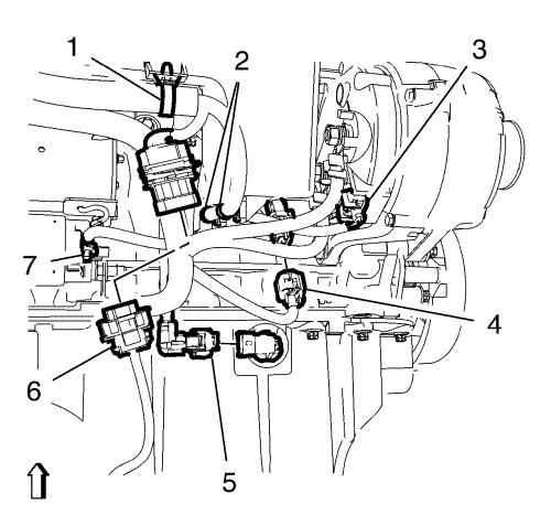
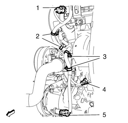
| 3. |
If equipped, disconnect the
engine oil level sensor wiring harness plug (5). |
| 4. |
Disconnect the generator
wiring harness plug (3). |
| 5. |
Remove the starter positive
cable nut (7) and remove the starter positive cable. |
| 6. |
Unclip the heated oxygen
sensor connection from the bracket and disconnect the heated oxygen
sensor wiring harness plug (6). |
| 7. |
Disconnect the knock sensor
wiring harness plug (4). |
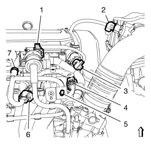
| 8. |
Unclip the 3 wiring harness
clips (1, 2) from the intake manifold. Hang the wiring harness
aside. |
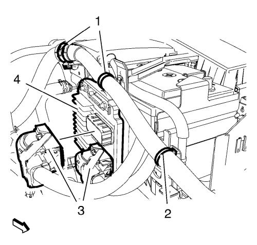
| 10. |
Disconnect the 2 engine
control module wiring harness plugs (3) from the engine control
module (4). |
| 11. |
Unclip the 3 wiring harness
clips (1, 2) from the engine control module wiring harness
brackets. |
| 12. |
Remove the engine control
module bracket along with the engine control module in top
direction from the battery tray. |
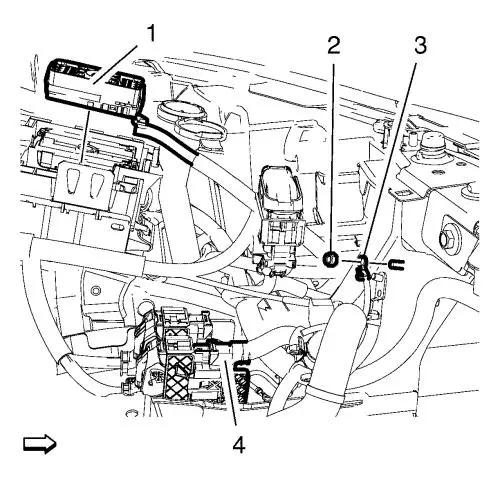
| 15. |
Remove the wiring harness
ground cable nut (2) and remove the wiring harness ground cable
(3). |
| 16. |
Remove the wiring harness plug
(1) in top direction from the front compartment fuse block
housing. |
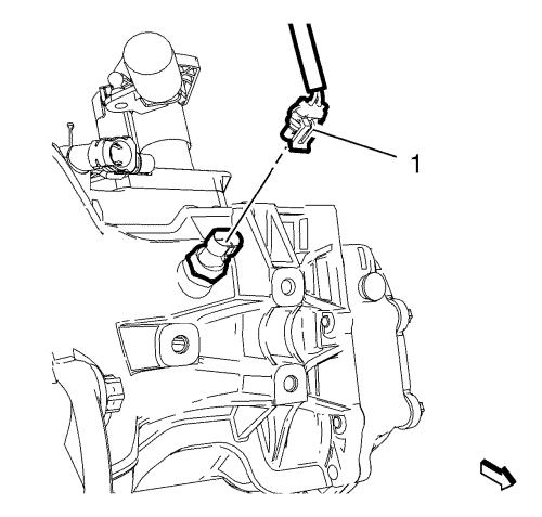
| 17. |
Disconnect the wiring harness
connection adapter plug (4). |
|
Note: Only necessary
for vehicles with manual transmission.
|
| 18. |
Disconnect the backup lamp
switch wiring harness plug (1). |
| 19. |
Disconnect the air
conditioning compressor wiring harness plug (5). |
| 20. |
Disconnect the engine oil
pressure indicator switch wiring harness plug (4). |
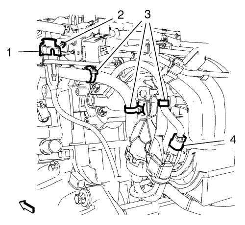
| 21. |
Unclip the 4 wiring harness
plugs (2, 3) from the brackets. |
| 22. |
Disconnect the exhaust
camshaft position actuator solenoid valve (1). |
| 23. |
Disconnect the mass air flow
sensor wiring harness plug (2) and unclip the wiring harness clip
in top direction from the air cleaner housing. |
| 24. |
Disconnect the intake camshaft
position actuator solenoid valve wiring harness plug (3).
|
| 25. |
Disconnect the evaporate
emission canister purge valve wiring harness plug (1). |
| 26. |
Disconnect the throttle body
wiring harness plug (4) and the manifold absolute pressure sensor
wiring harness plug (6). |
| 27. |
Unclip the wiring harness
clips (5, 7) from the brackets. |
| 28. |
Disconnect the intake manifold
tuning valve actuator check valve wiring harness plug (4).
|
| 29. |
Disconnect the crankshaft
position sensor wiring harness plug (1). |
| 30. |
Unclip the 4 wiring harness
clips (2, 3) from the brackets. |

| 31. |
Disconnect the heated oxygen
sensor wiring harness plug (7). |
| 32. |
Disconnect the coolant
thermostat wiring harness plug (6) and disconnect the 2 camshaft
position sensor wiring harness plugs (3, 8). |
| 33. |
Disconnect the engine coolant
temperature sensor wiring harness plug (4). |
| 34. |
Unclip the 3 wiring harness
clips (2, 5) from the wiring harness brackets. |
| 35. |
Remove the wiring harness
ground bolt (1) and remove the wiring harness ground cable.
|

| 36. |
Unclip the 2 engine wiring
harness clips (3, 4) from the brackets. |
| 37. |
Unclip the 2 engine wiring
harness conduits (2) in top direction from the camshaft
cover. |
| 38. |
Disconnect the ignition coil
wiring harness plug (1) and disconnect the fuel injector wiring
harness plug (5). |
| 39. |
Remove the engine control
module wiring harness from the vehicle. |
Installation Procedure
| 1. |
Position the engine control
module wiring harness to the vehicle. |
| 2. |
Connect the ignition coil
wiring harness plug (1) and connect the fuel injector wiring
harness plug (5). |
| 3. |
Clip the 2 engine wiring
harness conduits (2) to the camshaft cover. |
| 4. |
Clip the 2 engine wiring
harness clips (3, 4) to the brackets. |
| 5. |
Install the wiring harness
ground cable and the wiring harness ground cable bolt (1) and
tighten to 8 N·m (71 lb in) . |
| 6. |
Clip the 3 wiring harness
clips (2, 5) to the wiring harness brackets. |
| 7. |
Connect the engine coolant
temperature sensor wiring harness plug (4). |
| 8. |
Connect the coolant thermostat
wiring harness plug (6) and connect the 2 camshaft position sensor
wiring harness plugs (3, 8). |
| 9. |
Connect the heated oxygen
sensor wiring harness plug (7). |
| 10. |
Clip the 4 wiring harness
clips (2, 3) to the brackets. |
| 11. |
Connect the crankshaft
position sensor wiring harness plug (1). |
| 12. |
Connect the intake manifold
tuning valve actuator check valve wiring harness plug (4).
|
| 13. |
Clip the wiring harness clips
(5, 7) to the brackets. |
| 14. |
Connect the throttle body
wiring harness plug (4) and the manifold absolute pressure sensor
wiring harness plug (6). |
| 15. |
Connect the evaporate emission
canister purge valve wiring harness plug (1). |
| 16. |
Connect the intake camshaft
position actuator solenoid valve wiring harness plug (3).
|
| 17. |
Connect the mass air flow
sensor wiring harness plug (2) and clip the wiring harness clip to
the air cleaner housing. |
| 18. |
Connect the exhaust camshaft
position actuator solenoid valve (1). |
| 19. |
Clip the 4 wiring harness plug
(2, 3) to the brackets. |
| 20. |
Connect the engine oil
pressure indicator switch wiring harness plug (4). |
| 21. |
Connect the air conditioning
compressor wiring harness plug (5). |
|
Note: Only necessary
for vehicles with manual transmission.
|
| 22. |
Connect the backup lamp switch
wiring harness plug (1). |
| 23. |
Connect the wiring harness
connection adapter plug (4). |
| 24. |
Install the wiring harness
plug (1) to the front compartment fuse block housing. |
| 25. |
Install the wiring harness
ground cable (3) and install the wiring harness ground cable nut
(2) and tighten to 9 N·m (80 lb in)
. |
| 28. |
Install the engine control
module bracket along with the engine control module to the battery
tray. |
| 29. |
Connect the 2 engine control
module wiring harness plugs (3) to the engine control module
(4). |
| 30. |
Clip the 3 wiring harness
clips (1, 2) to the engine control module wiring harness
brackets. |
| 32. |
Clip the 3 wiring harness
clips (1, 2) to the intake manifold. |
| 33. |
Connect the knock sensor
wiring harness plug (4). |
| 34. |
Clip the heated oxygen sensor
connection to the bracket and connect the heated oxygen sensor
wiring harness plug (6). |
| 35. |
Install the starter positive
cable and the starter positive cable nut (7) and tighten to
12.5 N·m (111 lb in) . |
| 36. |
Connect the generator wiring
harness plug (3). |
| 37. |
If equipped, connect the
engine oil level sensor wiring harness plug (5). |
|
