Lubrication Description (LDC, LDD, LWD, L2I, L2N)
General Lubrication Description
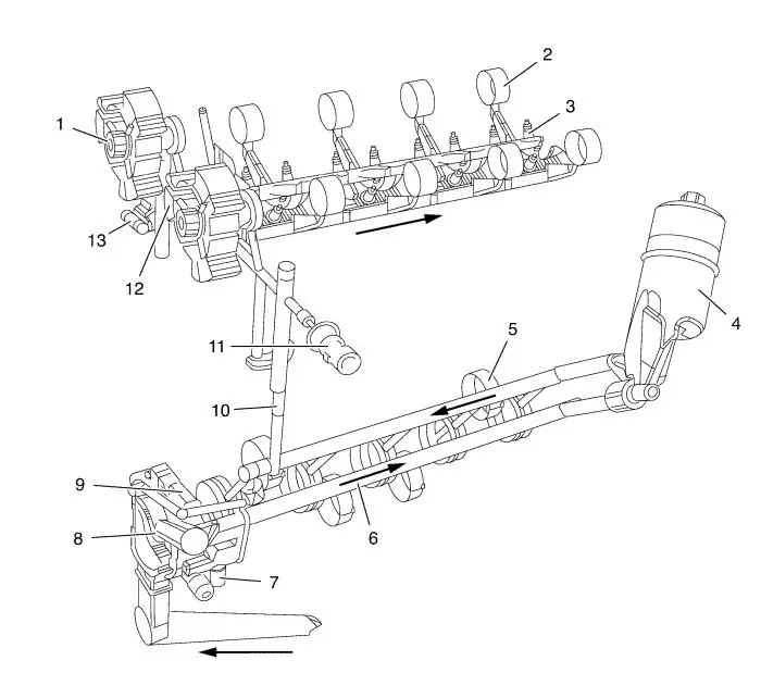
Oil is applied under pressure to the crankshaft bearings (6),
connecting rod bearings (5), camshaft bearings (2) and hydraulic
lash adjusters (3). In addition, the variable oil pump (8),
variable camshaft phaser (1), and hydraulic chain tensioner (13)
are supplied with pressurized oil. Oil is sucked from the oil pan
through the fixed screen into the variable vane type oil pump. The
pump is integrated in the front cover and directly driven by the
crankshaft. Also integrated into the front cover is a pressure
relieve valve (7) that opens when the oil pressure is too high at a
cold start. When that valve is open some oil flows directly into
the oil pan. Normally the pressurized oil passes into the engine
oil gallery leading to the oil filter module (4). The oil filter
module, with a burnable cartridge type filter, is located at the
rear left of the engine block and is serviceable from the top. The
oil enters the filter housing by passing a drain check valve. This
valve ensures that the oil cannot drain out of the filter module
when the engine is not operating. The oil is cleaned by passing the
filter from the outer to the inner side of the filter cartridge.
The oil then flows into the main oil gallery. A filter by-pass
valve in the oil filter module ensures that oil flows continues in
case the oil filter cartridge becomes restricted by more than 1.7
bar. When servicing the filter cartridge the oil remaining in the
filter module has to drain into the oil pan. This is done with an
integrated drain valve that opens when the oil filter cap is
opened. From the main gallery, the oil is distributed to the
crankshaft bearings, oil pump displacement control chamber (9) and
cylinder head feed (10). The connecting rod bearings are supplied
by oil flow passages through the crankshaft connecting the main
journals to the rod journals. A groove around each upper main
bearing furnishes oil to the drilled crankshaft passages. In the
cylinder head, the oil is distributed to the variable camshaft
phasers, chain tensioner, oil pressure switch (11) and through the
restrictor orifice (12) into the cam shaft feed oil gallery. From
there, the hydraulic valve lifters and camshaft bearings are
supplied with oil.
Variable Oil Pump Description
The engine is equipped with a variable displacement vane oil
pump. It is indirectly regulated by the oil pressure out of the
main oil gallery. The purpose of this indirect regulation is to
keep a defined maximum pressure in the main oil gallery independent
of the individual pressure drop between the pump outlet, the main
gallery inlet, and the various engine components. The purpose of
the variable displacement is to reduce the power consumption of the
pump to reduce the overall fuel consumption of the engine. The oil
flow of a static displacement oil pump is linear to the speed of
the pump. This would lead to an oil pressure that is too high at
certain engine speeds (ca. 1000 rpm at cold oil temperature, ca.
3000 rpm at hot oil temperatures). To reduce that high oil
pressure, normal pumps have a relieve valve: a portion of the
pressurized, already pumped oil is fed back to the intake of the
pump. This is a waste of power. The oil flow of a Variable
Displacement Vane Pump (VDVP), as used in Fam 0 Gen 3, is
non-linear to the speed and to the excentricity of the rotor to the
slide. The slide is moveable, so it is possible to reduce the oil
flow for a given speed by reducing the excentricity. With a lower
flow the oil pressure is reduced; pump oil flow equals now engine
oil flow.
|