Cylinder Head Replacement (1.4L LDD)
Special Tools
| • |
EN-470-B
Angular Torque Wrench |
| • |
EN-34730-91
Pressure Tester |
| • |
EN-955-1
Fixing Pin from EN-955 Kit |
For equivalent regional tools, refer to
Special Tools
Removal Procedure
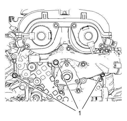
| 6. |
Unclip heater inlet hose from
2 retainer clips (1, 2). |
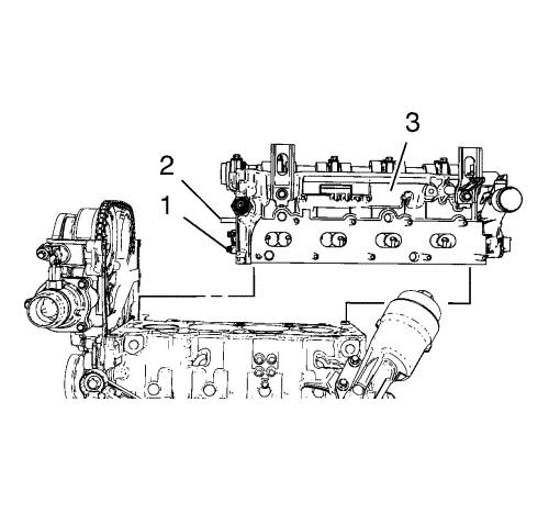
| 7. |
Disconnect engine control
module wiring harness from retainer clip (3). |
| 9. |
Lower vehicle by full
height. |
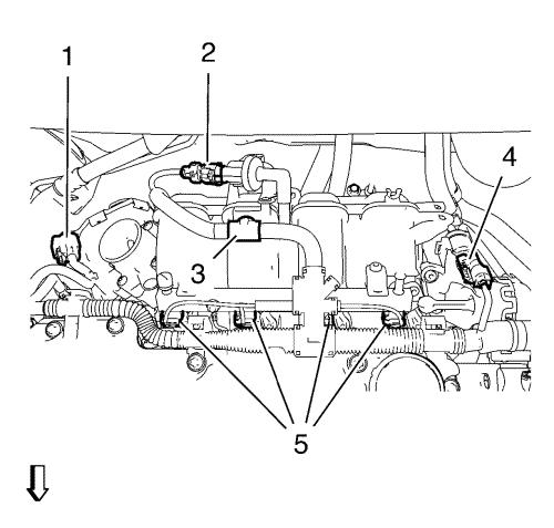
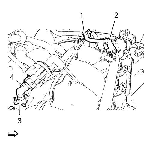
| 11. |
Disconnect engine control
module wiring harness from intake manifold upper: |
| |
• |
Disconnect throttle body
wiring harness plug (1). |
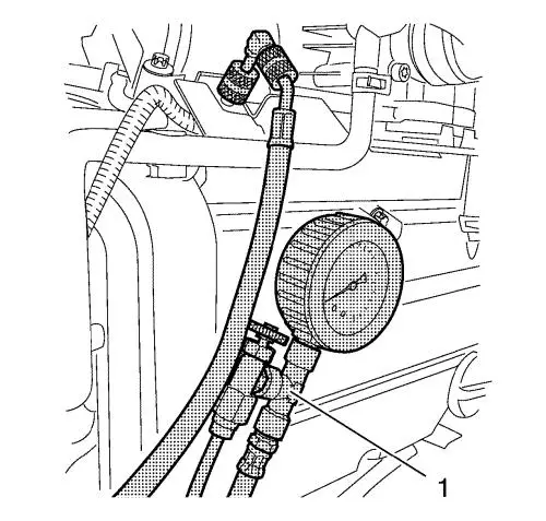
| |
• |
Disconnect evaporative
emission canister purge solenoid valve wiring harness plug
(2). |
| |
• |
Disconnect intake manifold
runner solenoid valve wiring harness plug (4). |
| |
• |
Unclip engine control module
wiring harness from intake manifold (3). |
| |
• |
Disconnect the 4 fuel injector
wiring harness plugs (5). |
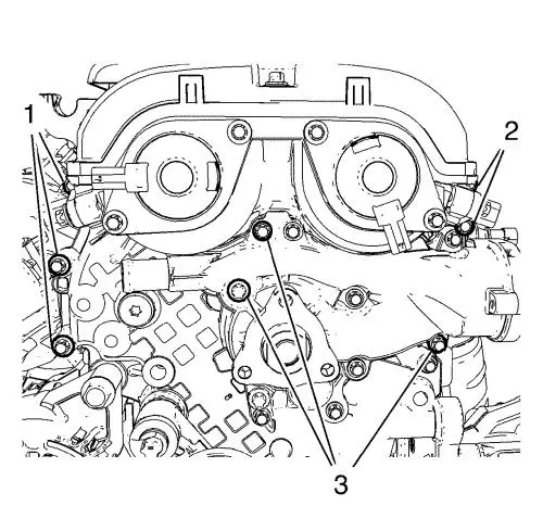
| 12. |
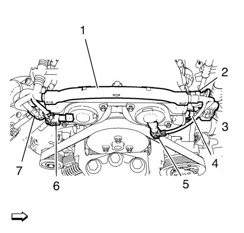
Remove engine control module
wiring harness (1) from camshaft cover: |
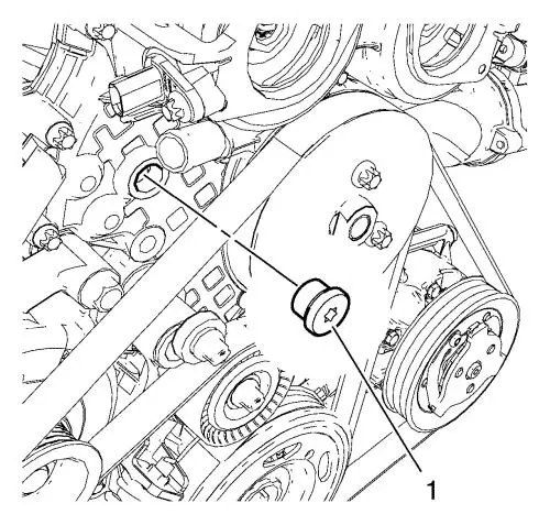
| |
• |
Disconnect intake camshaft
position sensor wiring harness plug (7). |
| |
• |
Disconnect intake camshaft
position actuator solenoid valve wiring harness plug (6).
|
| |
• |
Disconnect exhaust camshaft
position sensor wiring harness plug (4). |
| |
• |
Disconnect exhaust camshaft
position actuator solenoid valve wiring harness plug (5).
|
| |
• |
Disconnect engine coolant
temperature sensor wiring harness plug (3). |
| |
• |
Disconnect engine oil pressure
indicator switch wiring harness plug (2). |
| |
• |
Unclip engine control module
wiring harness (1) from camshaft cover. |
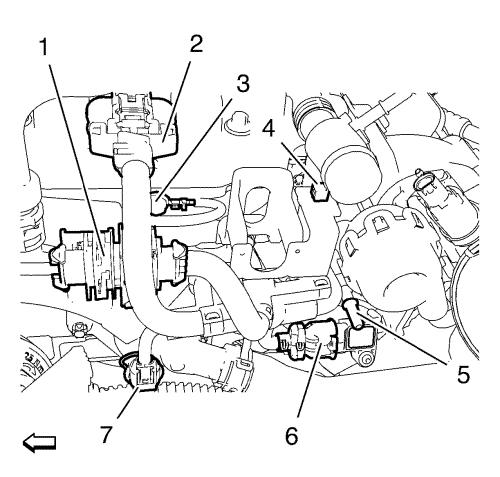
| 13. |
Unclip heated oxygen sensor
wiring harness plug (1) from retainer clip. |
| 14. |
Disconnect from engine coolant
temperature sensor wiring harness plug (7). |
| 15. |
Disconnect ignition coil
module wiring harness plug (2). |
| 16. |
Disconnect manifold absolute
pressure sensor wiring harness plug (6). |
| 17. |
Remove ground cable bolt (3)
and ground cable from cylinder head. |
| 18. |
Disconnect engine control
module wiring harness from retainer clip (4). |
| 19. |
Lay engine control module
wiring harness aside. |
| 20. |
Disconnect brake booster
vacuum pipe from intake manifold connector (5). |
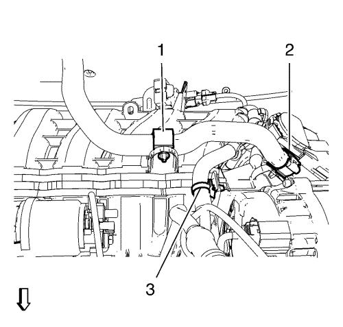
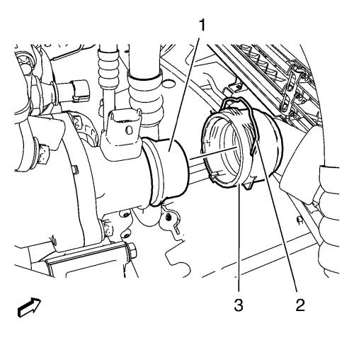
| 21. |
Remove radiator inlet hose
clamp (3). |
| 22. |
Remove radiator inlet hose (4)
from water outlet (2). |
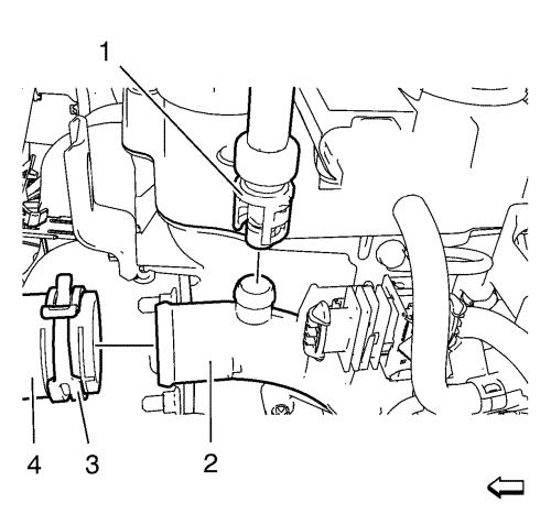
| 23. |
Remove engine coolant air
bleed hose (1) from water outlet (2). |
| 24. |
Remove heater inlet hose clamp
(1). |
| 25. |
Remove heater inlet hose (2)
from water outlet (3). |
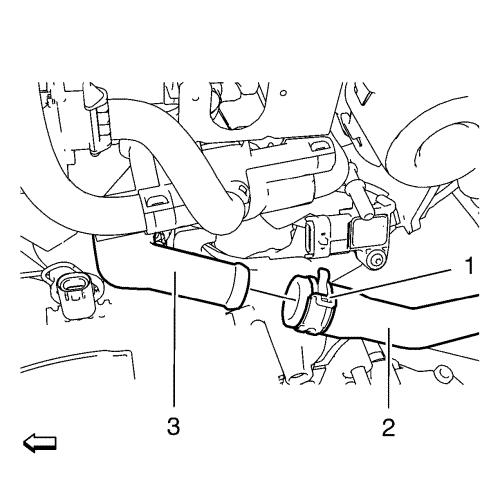
| 26. |
Unclip radiator outlet hose
quick connector clamp (2). |
| 27. |
Remove radiator outlet hose
(3) from engine coolant thermostat housing (1). |
| 28. |
Place collecting basin
underneath. |
| 29. |
Remove fuel injector rail cap
(1). |
| 30. |
Relief fuel pressure. Use
EN-34730-91 pressure tester (1). |
| 31. |
Remove fuel feed pipe (2) from
fuel injector rail. |
| 32. |
Unclip fuel feed pipe from
retainer clip (1). |
| 33. |
Remove fuel ventilation pipe
(4) from evaporative emission canister purge solenoid valve.
|
| 34. |
Unclip fuel ventilation pipe
from retainer clip (3). |
| 38. |
Remove 5 engine front cover
bolts (1, 2). |
| 39. |
Remove 3 water pump bolts
(3). |
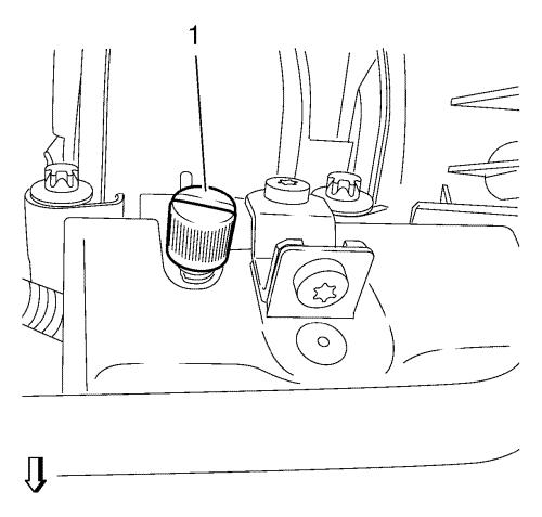
| 46. |
Remove the timing chain
tensioner plug (1) from the engine front cover. |
|
Note: Remove and
reinstall the EN-953-A fixing tool for this
step.
|
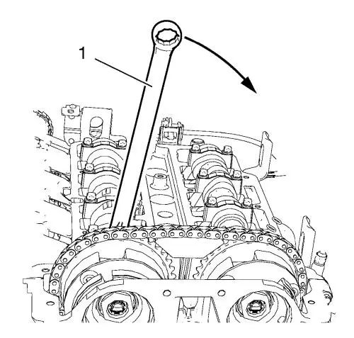
| 47. |
Install a spanner (1) to the
hexagon of the intake camshaft and rotate it in direction of the
arrow in order to apply tension to the timing chain and
hold. |
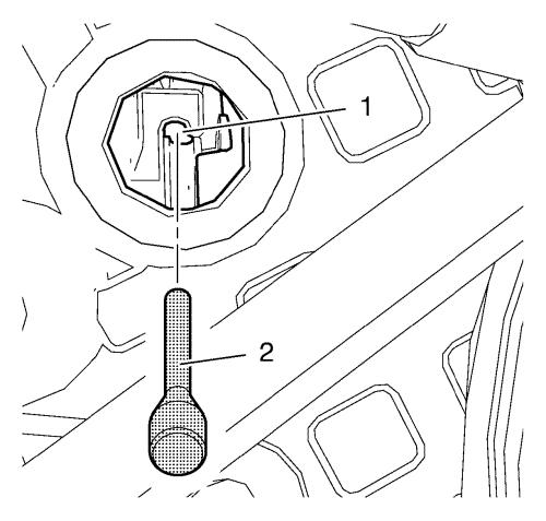
| 48. |
Install EN-955-1
pin (2) to the timing chain tensioner bore (1) in order to
fix it. |
| 49. |
Remove spanner from intake
camshaft. |
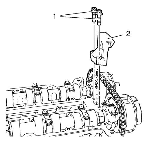
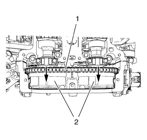
| 50. |
Remove 2 upper timing chain
guide bolts (1). |
| 51. |
Remove upper timing chain
guide (2). |
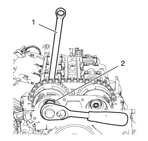
| 52. |
Loosen the intake camshaft
sprocket bolt (2) while holding up the hexagon of intake camshaft
sprocket with a spanner (1). |
| 53. |
Loosen the exhaust camshaft
sprocket bolt while holding up with a spanner. |
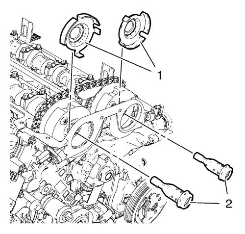
| 54. |
Remove the 2 camshaft sprocket
bolts (2) and the 2 camshaft position exciter wheels (1).
|
| 55. |
Remove the 2 camshaft
sprockets (2) in compound with the timing chain (1) and deposit in
engine front cover. |
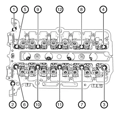
| 56. |
Loosen the 12 cylinder head
bolts in the sequence as shown. Use the following procedure:
|
| |
56.1 |
Loosen the cylinder head bolts
90° . |
| |
56.2 |
Loosen the cylinder head bolts
180° . |
| 57. |
Remove and DISCARD the 12
cylinder head bolts. |
| 58. |
Move the cylinder head
assembly slightly in direction of the transmission. |
|
Note: Mind the timing
chain tensioner and the timing chain guide pin. A second mechanic
is required.
|
| 59. |
Remove the cylinder head
assembly. |
| 60. |
Remove the cylinder head
gasket. |
| 61. |
Remove the assembly parts from
cylinder head: |
| |
• |
Remove the EN-953-A
fixing tool . |
| |
• |
Remove the engine oil pressure
indicator switch. |
| |
• |
Remove the 3 engine lift
brackets. |
Installation Procedure
| 1. |
Install the cylinder head
assembly parts: |
| |
• |
Install the 3 engine lift
brackets. |
| |
• |
Install the 3 engine lift
bracket bolts and tighten to 22 N·m (16 lb
ft) . |
| |
• |
Install the engine oil
pressure indicator switch and tighten to 20 N·m (15
lb ft) . |
|
Note: Adjust the camshafts
by means of the hexagon and a spanner.
|
| |
|
|
| |
• |
Install the EN-953-A
fixing tool . |
| 2. |
Cut the 2 elastomer sealing
lips (1) from engine front cover gasket. |
| 3. |
Bend down the engine front
cover gasket at the predetermined breaking points (arrows).
|
| 4. |
Clean sealing surfaces of
engine front cover and engine block from grease and old gasket
material. |
|
Note: Refer to
electronic parts catalogue to find a suitable sealing compound.
When sealing compound is applied, the complete fastening procedure
of the cylinder head should not take longer than 10 minutes.
|
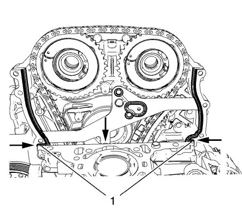
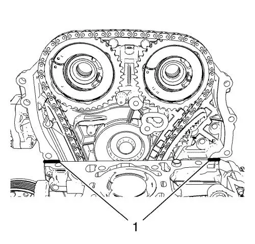
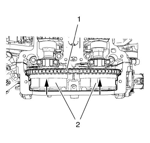
| 6. |
Apply sealing compound to the
shown areas (1). The thickness of the sealing bead should be
2 mm (0.0787 in) . |
|
Note: Mind the
marking on the cylinder head gasket for top side.
|
| 7. |
Install the cylinder head
gasket to engine block. |
| 8. |
Install 2 engine front cover
bolts (1) in order to guide the NEW upper engine front cover
gasket. |
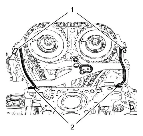
| 9. |
Install the NEW upper engine
front cover gasket. |
| 10. |
Apply sealing compound to the
shown areas (2). The thickness of the sealing bead should be
2 mm (0.0787 in) . |
|
Note: A second
mechanic is required. Guide the timing chain guide pin (2) to the
timing chain guide and the timing chain tensioner (1) with the
installed fixing pin through the timing chain tensioner plug bore
in engine front cover.
|
| 11. |
Install the cylinder head
(3). |
| 12. |
Loosely install 12 NEW
cylinder head bolts. |
| 13. |
Adjust the cylinder head to
the engine front cover. Use a rubber mallet. |
| 14. |
Prefix the engine front cover
to cylinder head by installing 3 bolts (1). |
| 15. |
Tighten the 3 bolts (1) to
8 N·m (71 lb in) . |
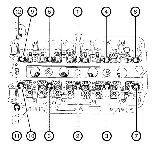
| 16. |
Tighten the cylinder head
bolts in the sequence as shown and in the following order:
|
| |
16.1 |
Tighten the cylinder head
bolts to 35 N·m(26 lb ft) . |
| |
16.2 |
Tighten the cylinder head
bolts an additional 180° . Use
EN-470-B wrench . |
| 17. |
Loosen the 3 bolts from engine
front cover. |
| 18. |
Install the 5 remaining bolts
to engine front cover and water pump. |
| 19. |
Tighten the 5 engine front
cover bolts (1, 2) to 8 N·m (71 lb in)
. |
| 20. |
Tighten the 3 water pump bolts
(3) to 8 N·m (71 lb in) . |
| 26. |
Install the 2 camshaft
sprockets (2) in compound with the timing chain (1). |
|
Note: Camshaft
position exciter wheels should stay rotatable.
|
| 27. |
Install the 2 camshaft
position exciter wheels (1) and the 2 camshaft sprocket bolts
(2). |
| 33. |
Clip fuel ventilation pipe to
retainer clip (3). |
| 34. |
Connect fuel ventilation pipe
(4) to evaporative emission canister purge solenoid valve.
|
| 35. |
Clip fuel feed pipe to
retainer clip (1). |
| 36. |
Connect fuel feed pipe (2) to
injector rail. |
| 37. |
Install fuel injector rail cap
(1). |
| 38. |
Connect radiator outlet hose
(3) to engine coolant thermostat housing (1). Clip quick connector
(2). |
| 39. |
Install heater inlet hose (2)
to water outlet (3). |
| 40. |
Install heater inlet hose
clamp (1). |
| 41. |
Install radiator inlet hose
(4) to water outlet (2). |
| 42. |
Install radiator inlet hose
clamp (3). |
| 43. |
Connect engine coolant air
bleed hose (1) to water outlet (2). |
| 44. |
Connect brake booster vacuum
pipe to intake manifold connector (5). |
| 45. |
Connect manifold absolute
pressure sensor wiring harness plug (6). |
| 46. |
Connect ignition coil module
wiring harness plug (2). |
| 47. |
Install ground cable and
ground cable bolt (3) to cylinder head and tighten to 8
N·m (71 lb in) . |
| 48. |
Connect engine coolant
temperature sensor wiring harness plug (7). |
| 49. |
Clip engine control module
wiring harness to retainer clip (4). |
| 50. |
Clip oxygen sensor wiring
harness plug (1) to retainer clip. |
| 51. |
Install engine control module
wiring harness to camshaft cover: |
| |
• |
Clip engine control module
wiring harness (1) to camshaft cover. |
| |
• |
Connect engine oil pressure
indicator switch wiring harness plug (2). |
| |
• |
Connect engine coolant
temperature sensor wiring harness plug (3). |
| |
• |
Connect exhaust camshaft
position actuator solenoid valve wiring harness plug (5).
|
| |
• |
Connect exhaust camshaft
position sensor wiring harness plug (4). |
| |
• |
Connect intake camshaft
position actuator solenoid valve wiring harness plug (6).
|
| |
• |
Connect intake camshaft
position sensor wiring harness plug (7). |
| 52. |
Connect engine control module
wiring harness to intake manifold upper: |
| |
• |
Connect the 4 fuel injector
wiring harness plugs (5). |
| |
• |
Clip the engine control module
wiring harness to intake manifold (3). |
| |
• |
Connect intake manifold runner
solenoid valve wiring harness plug (4). |
| |
• |
Connect the evaporative
emission canister purge solenoid valve wiring harness plug
(2). |
| |
• |
Connect the throttle body
wiring harness plug (1). |
| 54. |
Raise vehicle by full
height. |
| 56. |
Clip engine control module
wiring harness to retainer clip (3). |
| 57. |
Clip heater outlet hose to 2
retainer clips (1, 2). |
| 58. |
Lower vehicle by full
height. |
| 60. |
Connect battery negative
cable. |
| 62. |
Check and correct engine
oil. |
|
