Intake Manifold Replacement (LUH, LUJ w. El. Returnless Fuel
Syst.)
Special Tools
| • |
EN-34730-91
Pressure Tester |
For equivalent regional tools, refer to
Special Tools
Removal Procedure
| 3. |
Remove the engine sight
shield. |
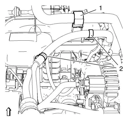
| 5. |
Unclip the heater outlet hose
from retainer clip (1). |
| 6. |
Unclip the engine control
module wiring harness from 2 retainer clips (2). |
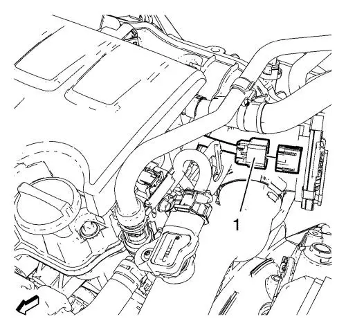
| 9. |
Disconnect the throttle body
wiring harness plug (1). |

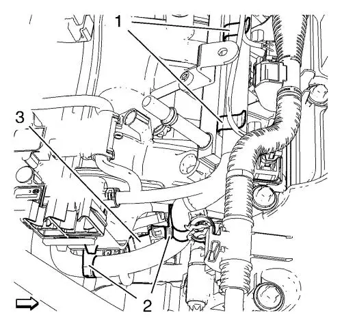
| 10. |
Disconnect the evaporative
emission canister purge solenoid valve wiring harness plug
(3). |
|
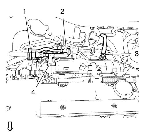
Note: Make note of
the installed position of the manifold absolute pressure sensor and
the barometric pressure sensor wiring harness plugs to ensure they
will be connected in their original position.
|
| 11. |
Disconnect the manifold
absolute pressure sensor wiring harness plug (2) and the barometric
pressure sensor wiring harness plug (1). |
| 12. |
Disconnect the 4 fuel injector
wiring harness plugs (4). |
| 13. |
Unclip the engine control
module wiring harness from the camshaft cover. |
| 14. |
Disconnect the turbocharger
wastegate regulator solenoid valve wiring harness plug (3).
|
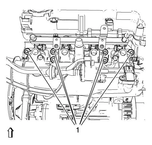
| 15. |
Unclip the engine control
module wiring harness from 2 intake manifold retainer clips (2) and
from 2 fuel injection rail retainer clips (1). |
|
Warning:
Gasoline or gasoline vapors are highly flammable.
A fire could occur if an ignition source is present. Never drain or
store gasoline or diesel fuel in an open container, due to the
possibility of fire or explosion. Have a dry chemical (Class B)
fire extinguisher nearby. |
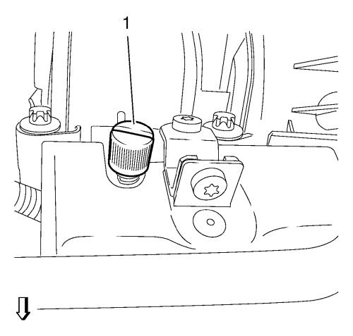
| 16. |
Remove the fuel injector rail
cap (1). |
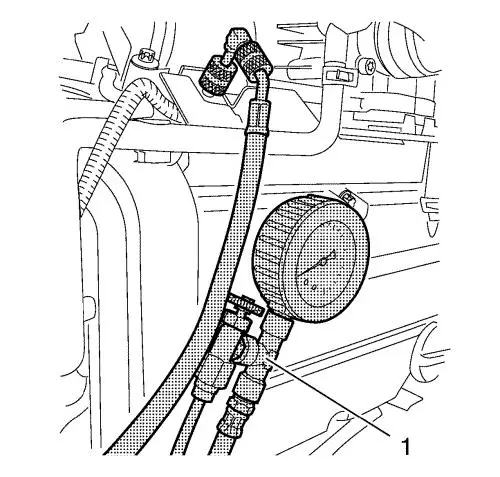
| 17. |
Relieve the fuel pressure,
using the EN-34730-91 pressure tester (1).
|
| 18. |
Remove the fuel feed pipe (4)
from fuel injector rail. |
| 19. |
Unclip the fuel feed pipe from
retainer clip (1). |
| 20. |
Remove the fuel ventilation
pipe (2) from evaporative emission canister purge solenoid
valve. |
| 21. |
Unclip the fuel ventilation
pipe from retainer clip (1). |
| 22. |
Close the vents with the
EN-6015 closure plugs . |
| 23. |
Disconnect the brake booster
vacuum pipe (3) from the intake manifold. |
|
Note: The intake
manifold bolts remain in intake manifold.
|
| 24. |
Remove the 6 intake manifold
bolts (1). |
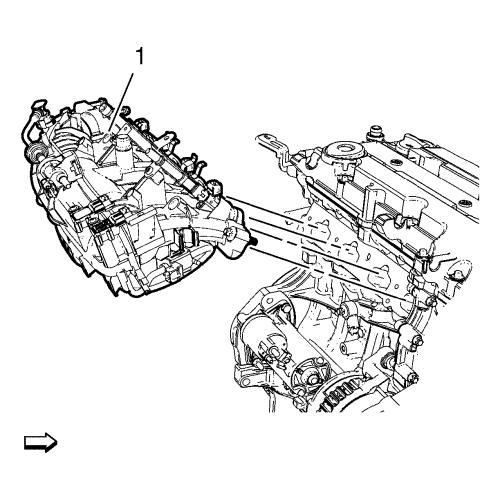
| 25. |
Remove the intake manifold (1)
in compound with the intake manifold gasket. |
Installation Procedure
| 2. |
Clean the sealing
surfaces. |
| 3. |
Install the intake manifold
(1) along with a NEW intake manifold gasket. |
| 4. |
Install the 6 intake manifold
bolts (1) and tighten to 20 N·m (15 lb ft)
. |
| 5. |
Connect the fuel ventilation
pipe (2) to the evaporative emission canister purge solenoid
valve. |
| 6. |
Clip in the fuel ventilation
pipe to the retainer clip (1). |
| 7. |
Connect the fuel feed pipe (4)
to the injector rail. |
| 8. |
Clip in the fuel feed pipe to
the retainer clip (1). |
| 9. |
Connect the brake booster
vacuum pipe (3) to the intake manifold. |
| 10. |
Install the fuel injector rail
cap (1). |
| 11. |
Connect the turbocharger
wastegate regulator solenoid valve wiring harness plug (3).
|
| 12. |
Clip in the engine control
module wiring harness to 2 intake manifold retainer clips (2) and
from 2 fuel injection rail retainer clips (1). |
| 13. |
Clip in the engine control
module wiring harness to the camshaft cover. |
| 14. |
Connect the 4 fuel injector
wiring harness plugs (4). |
| 15. |
Connect the manifold absolute
pressure sensor wiring harness plug (2) and the barometric pressure
sensor wiring harness plug (1). |
| 16. |
Disconnect the evaporative
emission canister purge solenoid valve wiring harness plug
(3). |
| 17. |
Connect the throttle body
wiring harness plug (1). |
| 19. |
Raise and support the
vehicle. |
| 20. |
Clip in the heater outlet hose
to retainer clip (1). |
| 21. |
Clip in the engine control
module wiring harness to 2 retainer clips (2). |
| 23. |
Install the engine sight
shield. |
|
