Valve Guide Reaming, and Valve and Seat Grinding
Valve Cleaning Procedure
| 1. |
Use soft bristle wire brush to
clean any carbon build-up from the valve head. DO NOT use a wire
brush on any part of the valve stem. The valve stem is chrome
plated to provide enhanced wear characteristics. Wire brushing the
stem could remove the chrome plating. |
| 2. |
Thoroughly clean the valve
with solvent and wipe dry. |
Valve Visual Inspection Procedure
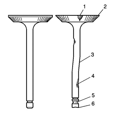
| 1. |
Inspect the valve for damage
from the head to tip for the following conditions: |
| |
• |
Pitting in the valve seat area
(1) |
| |
• |
Lack of valve margin
(2) |
| |
• |
Bending in the valve stem
(3) |
| |
• |
Pitting or excessive wear in
the stem (4) |
| |
• |
Worn valve key grooves
(5) |
| 2. |
Replace the valve if any of
these conditions exist. |
Valve Measurement and Reconditioning Overview
Note:
| • |
Proper valve
service is critical to engine performance. Therefore, all detailed
measurement procedures must be followed to identify components that
are out of specification. |
| • |
If the measurement
procedures reveal that the valve or valve seat must be
reconditioned, it is critical to perform the measurement procedures
after reconditioning. |
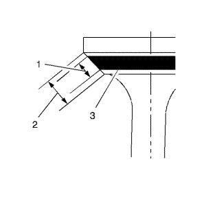
Valve Seat Width Measurement Procedure
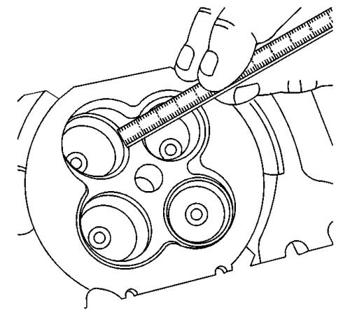
| 1. |
Measure the valve seat width
in the cylinder head using a proper scale. |
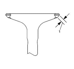
| 2. |
Measure the seat width on the
valve face (1) using a proper scale. |
|
Note: The seat
contact area must be at least 0.5 mm (0.020 in) from the outer
diameter (margin) of the valve. If the contact area is too close to
the margins, the seat must be reconditioned to move the contact
area away from the margin.
|
| 4. |
If the seat widths are
acceptable, check the valve seat roundness using the Valve Seat
Roundness Measurement Procedure. |
| 5. |
If the seat width is not
acceptable, you must grind the valve seat using the Valve and Seat
Reconditioning Procedure to bring the width back into
specification. Proper valve seat width is critical to providing the
correct amount of valve heat dissipation. |
Valve Seat Roundness Measurement Procedure
| 1. |
Measure the valve seat
roundness using a dial indicator attached to a tapered pilot
installed in the guide. The pilot should have a slight bind when
installed in the guide. |
|
Caution: The correct size pilot must be used. Do not use
adjustable diameter pilots. Adjustable pilots may damage the valve
guides. |
| 3. |
If the valve seat exceeds the
roundness specification, you must grind the valve and valve seat
using the Valve and Seat Reconditioning Procedure. |
| 4. |
If new valves are being used,
the valve seat roundness must be within 0.05 mm (0.002
in). |
Valve Margin Measurement Procedure
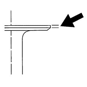
| 1. |
Measure the valve margin using
an appropriate scale. |
| 2. |
Reference the specifications
in this section for minimum valve margin and compare them to your
measurements. |
| 3. |
If the valve margins are
beyond specification, replace the valves. |
| 4. |
If the valve margins are
within specification and do not require refacing, test the valve
for seat concentricity using the Valve-to-Seat Concentricity
Measurement Procedure. |
Valve-to-Seat Concentricity Measurement Procedure
|
Note:
| • |
Checking the
valve-to-seat concentricity determines whether the valve and seat
are sealing properly. |
| • |
You must measure
the valve face and the valve seat to ensure proper valve
sealing. |
|
| 1. |
Coat the valve face lightly
with blue dye (3). |
| 2. |
Install the valve in the
cylinder head. |
| 3. |
Turn the valve against the
seat with enough pressure to wear off the dye. |
| 4. |
Remove the valve from the
cylinder head. |
| 5. |
Inspect the valve face.
|
| |
|
|
| |
• |
If the valve face is
concentric, providing a proper seal, with the valve stem, a
continuous mark will be made around the entire face (1).
|
|
Note: The wear mark MUST be
at least 0.5 mm (0.020 in) from the outer diameter, the
margin, of the valve. If the wear mark is too close to the margin,
the seat must be reconditioned to move the contact area away from
the margin.
|
| |
• |
If the face is not concentric
with the stem, the mark will NOT be continuous around the valve
face. The valve should be refaced or replaced and the seat must be
reconditioned using the Valve and Seat Reconditioning
Procedure. |
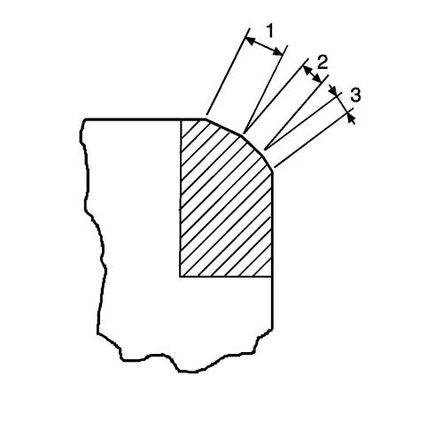
Valve and Seat Reconditioning Procedure
|
Note:
| • |
If the valve seat
width, roundness or concentricity is beyond specifications, you
must grind the seats in order to ensure proper heat dissipation and
prevent the build up of carbon on the seats. |
| • |
It is necessary to
reface the valve if seat reconditioning is required unless a new
valve is used. |
|
| 2. |
Using the proper angle
specification, refer to
Engine Mechanical Specifications , grind, relieve, the valve
seats (1) to correctly position the valve seating surface (2) to
the valve. |
| 4. |
If the original valve is being
used, grind the valve to the specifications, refer to
Engine Mechanical Specifications . Measure the valve margin
again after grinding using the Valve Margin Measurement Procedure.
Replace the valve if the margin is out of specification. New valves
do not require grinding. |
| 5. |
When grinding the valves and
seats, grind off as little material as possible. Cutting valve seat
results in lowering the valve spring pressure. |
| 6. |
Install the valve in the
cylinder head. |
| |
|
|
| |
• |
If you are using refaced
valves, lap the valves into the seats with a fine grinding
compound. The refacing and reseating operations should leave the
refinished surfaces smooth and true so that minimal lapping is
required. Excessive lapping will groove the valve face and prevent
a good seat when hot. |
|
Note: Be sure to clean any
remaining lapping compound from the valve and seat with solvent and
compressed air prior to final assembly.
|
| |
• |
If you are using new valves,
do not lap the valves under any condition. |
| 7. |
After obtaining the proper
valve seat width in the cylinder head, you must re-measure the
valve stem height using the Valve Stem Height Measurement
Procedure. |
| 8. |
If the valve stem height is
acceptable, test the seats for concentricity using the
Valve-to-Seat Concentricity Measurement Procedure. |
Valve Stem Height Measurement Procedure
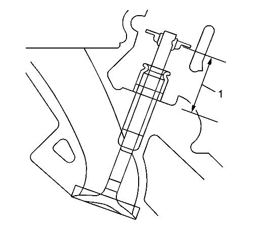
|
Note: To determine
the valve stem height measurement, measure from the valve spring
seat to the valve spring retainer.
|
| 1. |
Install the valve into the
valve guide. |
| 2. |
Ensure the valve is seated to
the cylinder head valve seat. |
| 3. |
Install the valve stem oil
seal. |
| 4. |
Install the valve spring
retainer and valve stem locks. |
| 6. |
If the maximum height
specification is exceeded, a new valve should be installed and the
valve stem height re-measured. |
|
Caution: DO
NOT grind the valve stem tip. The tip of the valve is hardened and
grinding the tip will eliminate the hardened surface causing
premature wear and possible engine damage. |
|
Caution: DO
NOT use shims in order to adjust valve stem height. The use of
shims will cause the valve spring to bottom out before the camshaft
lobe is at peak lift and engine damage could result. |
| 7. |
If the valve stem height still
exceeds the maximum height specification, the cylinder head must be
replaced. |
|
