Valve Stem Oil Seal and Valve Spring Replacement
Special Tools
| • |
EN-6086 Basic
Kit, Spring and Wedge Replacer |
| • |
EN-6625
Flywheel Holder |
For equivalent regional tools, refer to
Special Tools .
Removal Procedure
|
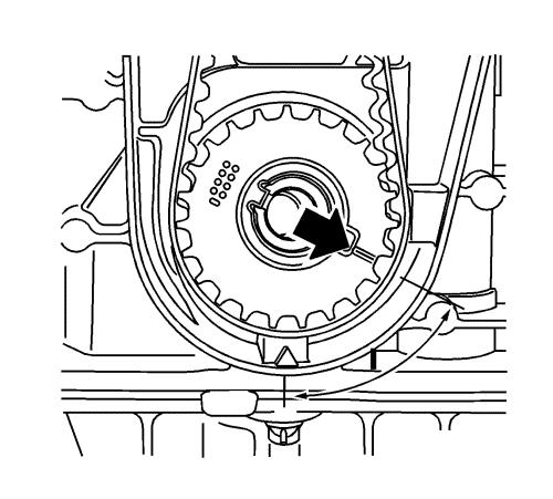
Note: 180° offset
to marking ignition TDC cylinder number 1.
|
| 3. |
Make alignment mark on the
toothed belt drive belt. |
| 4. |
Turn the crankshaft to
ignition TDC marking, cylinder number 1. |
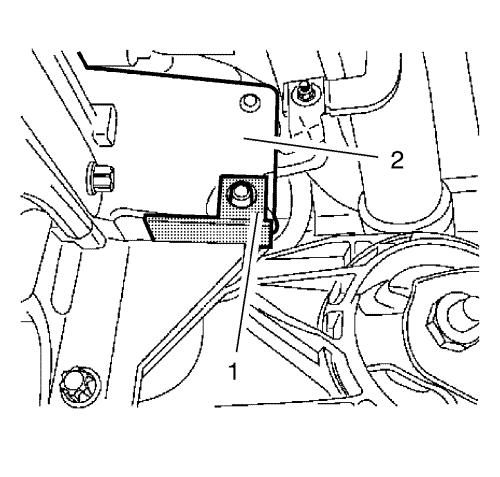
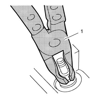
| 7. |
Install EN-6625
flywheel holder (1) to the engine block (2). |
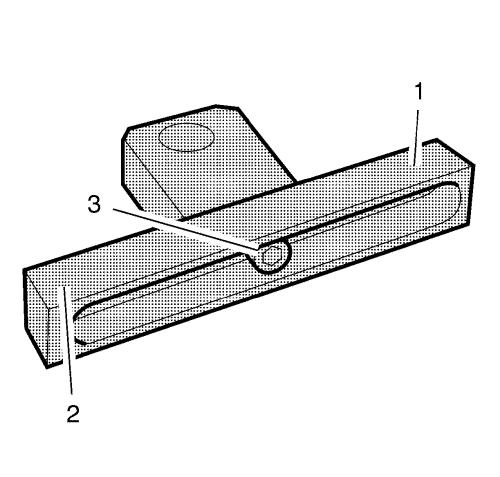
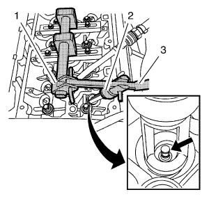
| 10. |
Tighten one of the support
head (1) in the center of the rail (2) with the fastener
(3). |
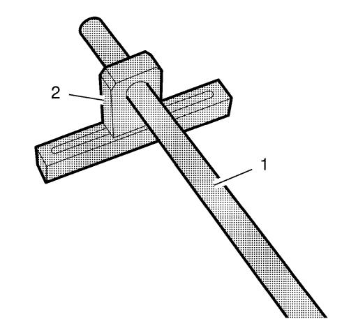
| 11. |
Install the EN-6086-5
mounting shaft (1) to one of the EN-6086-6
support (2). |
| 12. |
Install the second support to
the mounting shaft. |
| 13. |
Install the lever arm bracket
to the cylinder head. |
| 14. |
Attach the EN-6086-15
pneumatic adapter (1). |
| |
14.1 |
Attach the adapter to cylinder
number 1. |
| |
14.2 |
Apply compressed air to
cylinder number 1. |
| 15. |
Attach the EN-6086-7
lever arm (3). |
| |
15.1 |
Complete the lever arm with
the EN-6086-8 joint (1) and the EN-6086-11
removal head (2). |
|
Note: Removal head must
point toward the intake side.
|
| |
15.2 |
Slide assembly on installation
shaft over the 1st cylinder. |
| 16. |
Remove the intake valve
springs, 1st cylinder. |
|
Note: Removal head must be
positioned vertically over the valve stem.
|
| |
16.2 |
Carefully push the valve
springs down using the EN-6086-7 lever arm .
|
|
Note: Observe correct
assignment.
|
| |
16.3 |
Remove the valve
keepers. |
| |
16.4 |
Remove the valve head and the
valve springs. |
| 17. |
Remove the valve stem
seals. |
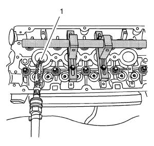
| |
Remove the valve stem seals with the EN-840
remover (1). |
| 18. |
Install the valve stem
seals. |
| |
18.1 |
Coat the valve stem with
engine oil. |
| |
18.2 |
Connect the new valve stem
seals onto valve stem. |
| |
18.3 |
Using the EN-958
installer , drive home to limit stop. |
|
Note: Note
manufacturer provisions.
|
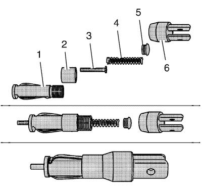
| 19. |
Complete the
EN-6086-200-1 assembly head . |
| |
19.1 |
Use the
EN-6086-200-10 thrust piece . |
| |
19.2 |
Put together the assembly head
consisting of mount (1), fixing sleeve (2), thrust piece (3),
spring (4), screw fixing (5) and lever mount (6). |
| 20. |
Install the intake valve
springs, 1st cylinder. |
| |
20.1 |
Insert the valve springs and
valve head. |
|
Note: Insert the valve
cotters with the tapered end toward the valve.
|
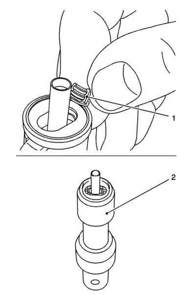
| |
20.2 |
Insert the valve cotters (1)
in the EN-6086-200-1 assembly head . |
| • |
Slide the plastic clamping sleeve (2) in the direction of the
lever arm mount. |
| • |
Push the plastic clamping sleeve toward the valve. |
|
Note: Assembly head must
stand vertically above the valve stem. Valve cotters must engage
audibly.
|
| |
20.3 |
Attach the assembly head to
the lever arm. |
| |
20.4 |
Carefully push the valve
spring down using the EN-6086-7 lever arm .
|
|
Note: Do not make 2nd
attempt without inspecting that both valve cotters are seated in
the assembly head.
|
| 21. |
Inspect installation
position. |
| |
Inspect seating of the valve keepers (visual inspection). |
| 22. |
Transfer the
EN-6086-7 lever arm . |
| |
22.1 |
Remove the lever arm.
|
| |
22.2 |
Detach the assembly
head. |
|
Note: Removal head must
point toward the exhaust side.
|
| |
22.3 |
Attach the removal
head. |
| |
22.4 |
Install the lever arm.
|
| 23. |
Remove the exhaust valve
springs, 1st cylinder. |
| |
23.1 |
Carefully push the valve
springs down using the EN-889-12 lever arm .
|
|
Note: Removal head must be
positioned vertically over the valve stem.
|
| |
23.2 |
Remove the valve
keepers |
|
Note: Observe correct
assignment.
|
| |
23.3 |
Remove the valve head and
valve springs. |
| 24. |
Replace the valve stem
seals. |
| |
24.1 |
Pull off with the
EN-840 remover . |
| |
24.2 |
Coat the valve stem with
engine oil. |
| |
24.3 |
Connect the new valve stem
seals onto the valve stem. |
| |
24.4 |
Using the EN-958
installer , drive home to limit stop. |
| 25. |
Attach the EN-6086-7
lever arm . |
| |
25.1 |
Insert the valve springs and
valve head. |
| |
25.2 |
Insert the valve wedges in the
EN-889-2 assembly head . |
| • |
Note: Insert the
valve cotters with the tapered end toward the valve.
|
| • |
Push the plastic clamping sleeve toward the lever arm
mounting. |
| • |
Push the plastic clamping sleeve toward the valve. |
|
Note: Assembly head must
stand vertically above the valve stem. Valve cotters must engage
audibly.
|
| |
25.3 |
Attach the assembly head to
the lever arm. |
|
Note: Do not make 2nd
attempt without inspecting that both valve cotters are seated in
the assembly head.
|
| |
25.4 |
Carefully push the valve
spring down using the EN-889-12 lever arm .
|
| 26. |
Inspect installation
position. |
| |
Inspect seating of the valve keepers (visual inspection). |
| 27. |
Transfer the
EN-6086-15 pneumatic adapter . |
| |
27.1 |
Interrupt the compressed air
feed. |
| |
27.2 |
Remove the adapter from
cylinder number 1. |
| |
27.3 |
Install the adapter to
cylinder number 4. |
| |
27.4 |
Apply compressed air to
cylinder number 4. |
| 28. |
Replace the valve stem seal of
cylinder 4 by analogy with step 14 - 21. |
| 29. |
Remove the EN-6086-15
pneumatic adapter . |
| |
29.1 |
Interrupt the compressed air
feed. |
| |
29.2 |
Remove the adapter from
cylinder number 4. |
| 30. |
Raise and support the
vehicle. |
| 31. |
Remove EN-6625
holder from the engine block. |
| 32. |
Set the crankshaft to ignition
TDC of cylinder 3. |
|
Note: Alignment
marking on toothed belt drive wheel must align with marking on rear
toothed belt cover.
|
| 33. |
Turn crankshaft evenly by
180°. |
| 34. |
Block the crankshaft.
|
| 35. |
Install EN-6625
holder to the engine block. |
| 37. |
Replace the valve stem seal of
cylinders 2 and 3 by analogy with step 7 to step 21. |
| 38. |
Remove the EN-6086-15
pneumatic adapter . |
| |
38.1 |
Interrupt the compressed air
feed. |
| |
38.2 |
Remove the adapter from
cylinder number 3. |
| 39. |
Remove the EN-6086
automatic valve spring lever . |
| |
39.1 |
Release the installation
shaft. |
| |
39.2 |
Remove both supports with the
installation shaft. |
| |
39.3 |
Remove the installation head
from the lever arm. |
Installation Procedure
| 2. |
Remove EN-6625
holder from the engine block. |
| 3. |
Set the engine to 60°
(measurement l) before TDC. |
| 4. |
Set the crankshaft in
direction of engine rotation to 60° (measurement l) before
TDC. |
|
