Timing Belt Adjustment (LDE, LED, LFJ, LXV, 2H0, LUW, LFH)
Special Tools
| • |
EN-45059
Torque Angle Sensor Kit |
For equivalent regional tool, refer to
Special Tools .
Removal Procedure
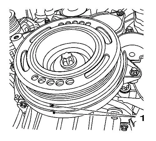
| 2. |
Set the crankshaft balancer in
the direction of the engine rotation to "1st cylinder TDC" (mark
1). |
|
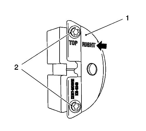
Note: The right half
of the EN-6340 locking tool can be recognised by
the lettering "right", arrow, on the tool.
|
| 4. |
Prepare the right half of the
EN-6340 locking tool . |
| |
4.1 |
Remove the 2 bolts (2).
|
| |
4.2 |
Remove the front panel (1)
from the EN-6340 locking tool - right. |
|
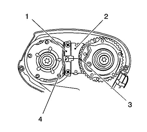
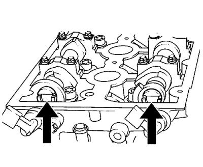
Note:
| • |
The spot type
marking (4) on the intake camshaft position actuator adjuster does
not correspond to the groove of the EN-6340 locking
tool - left (1) during this process, but must be somewhat
above. |
| • |
The spot type
marking (3) on the exhaust camshaft position actuator adjuster must
correspond to the groove on EN-6340 locking tool -
right (2). |
|
| 5. |
Insert the EN-6340
locking tool - left (1) and the EN-6340
locking tool - right (2) in the camshaft position actuator
adjuster. |
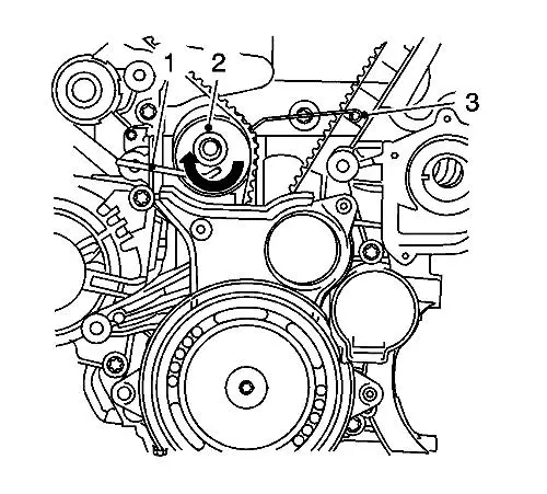
| 6. |
Install the EN-6333
locking pin (1), apply tension to the timing belt tension
roller (2) in the direction of the arrow. Install the
EN-6333 locking pin (3). |
| 7. |
Mark timing belt in direction
of rotation. |
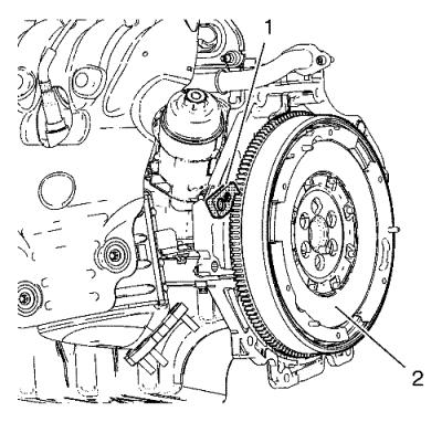
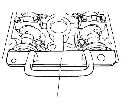
| 8. |
Install the EN-652
flywheel holder (1), lock the flywheel (2) (or automatic
transmission flex respectively) via the starter ring gear.
|
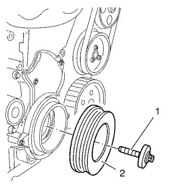
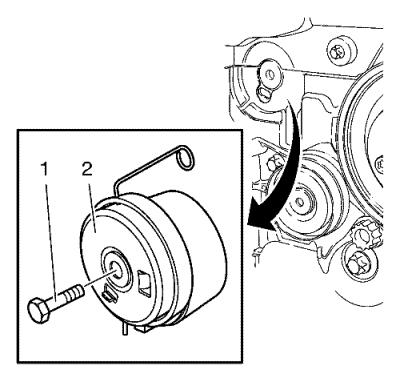
| 9. |
Remove and DISCARD the
crankshaft balancer bolt (1). |
| 10. |
Remove the crankshaft balancer
(2). |
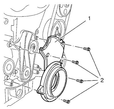
| 11. |
Remove the 4 timing belt lower
front cover bolts (2). |
| 12. |
Remove the timing belt lower
front cover (1). |
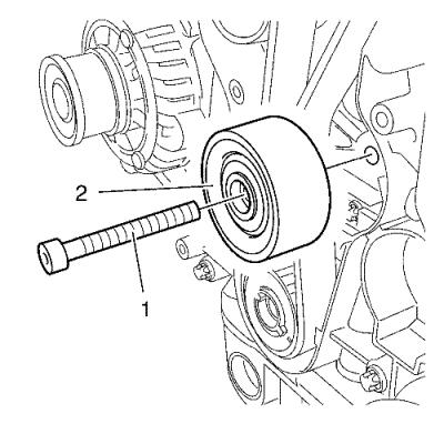
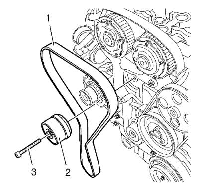
| 13. |
Remove the timing belt idler
pulley bolt (1). |
| 14. |
Remove the timing belt idler
pulley (2). |
| 15. |
Remove the tensioner bolt
(1). |
| 16. |
Remove the timing belt
tensioner (2). |
| 17. |
Remove the timing belt
(1). |
| 18. |
Stop the timing belt tensioner
(2). |
| 19. |
Remove the EN-652
flywheel holder to unlock the crankshaft. |
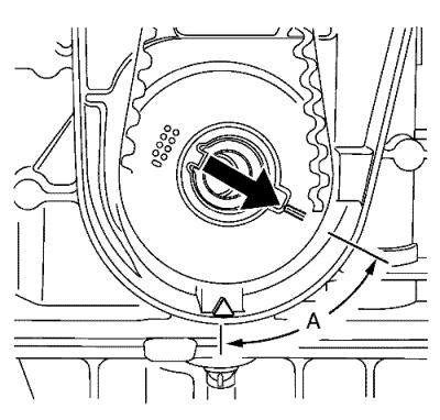
| 20. |
Turn the crankshaft 60°
(A) against the direction of engine rotation. |
| 21. |
Remove the 2 camshaft position
actuator adjuster closure bolts (1). |
|
Note: A second
technician is required.
|
| 22. |
Loosen the camshaft position
actuator adjuster bolts (2). |
| |
Hold at the appropriate camshaft hexagon. |
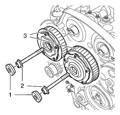
| 23. |
Remove and DISCARD the
camshaft position actuator adjuster bolts (2) and the camshaft
position actuator adjuster (3). |
| 24. |
Align the camshafts
horizontally by the hexagon arrows, until the EN-6628-A
locking tool can be inserted in both camshafts. |
| 25. |
Insert the EN-6628-A
locking tool (1) into the camshafts. |
Installation Procedure
|
Note: Do not tighten
the camshaft adjuster bolts.
|
| 1. |
Install the camshaft position
actuator adjuster (3). |
| 2. |
Install NEW camshaft position
actuator adjuster bolts (2). |
|
Note: A second
technician is required.
|
| 3. |
Tighten the camshaft position
actuator adjuster bolts (2) in three passes: |
| |
Hold at the appropriate camshaft hexagon. |
| |
3.1 |
First pass tighten to
65 N·m (48 lb ft) . |
| |
3.2 |
Second pass to
120° . |
| 4. |
Replace the camshaft position
actuator adjuster seal rings. |
| 5. |
Install the 2 camshaft
position actuator adjuster closure plugs (1) and tighten to
30 N·m (22 lb ft) . |
| 6. |
Remove the EN-6628-A
locking tool . |
| 7. |
Clean the timing belt
tensioner thread. |
| 8. |
Install the timing belt
tensioner (2) and tighten the NEW timing belt tensioner bolt (1) to
20 N·m (15 lb ft) . |
| 9. |
Clean the timing belt idler
pulley thread. |
| 10. |
Install the timing belt idler
pulley (2) and tighten the NEW bolt (1) to 25 N·m
(18 lb ft) . |
|
Note: The timing belt
drive gear and oil pump housing must align.
|
| 11. |
Turn the crankshaft in the
direction of engine rotation, by the crankshaft balancer bolt, to
cylinder 1 TDC of combustion stroke. |
| 12. |
Install the EN-652
flywheel holder (1), lock the flywheel (2) (or automatic
transmission flex respectively) via the starter ring gear.
|
|
Note: Observe
direction of rotation.
|
| 13. |
Insert the timing belt
(1). |
| 14. |
Apply preliminary tension
clockwise to the timing belt tension roller. |
| 15. |
Remove the EN-6333
locking pin . |
| 16. |
Release the tension on the
timing belt tensioner. |
| 17. |
Install the lower front timing
belt cover (1) and tighten the 4 bolts (2) to 6 N·m
(53 lb in) . |
| 18. |
Install the crankshaft
balancer (2) and NEW bolt (1) and tighten in 3 passes using the
EN-45059 sensor kit : |
| |
18.1 |
First pass to 95
N·m (70 lb ft) . |
| |
18.2 |
Second pass to
45° . |
| 19. |
Remove the EN-652
flywheel holder to unlock the crankshaft. |
| 20. |
Remove the EN-6340
locking tool . |
| 21. |
Check position of the camshaft
position actuator adjuster. |
| |
21.1 |
Turn crankshaft
720° in the direction of engine rotation by
the crankshaft balancer bolt. |
|
Note: Note marking,
camshaft position actuator adjuster.
|
| |
21.2 |
Insert EN-6340
locking tool into camshaft timing gears. |
| 22. |
Insert the EN-6628-A
locking tool (1) into the camshafts. |
| 23. |
Align camshafts by hexagon
until EN-6628-A locking tool can be inserted in
both camshafts. |
| 24. |
Check the crankshaft
position. |
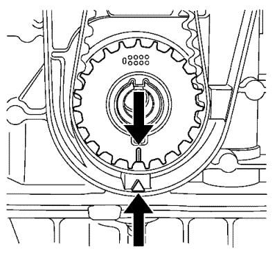
| 25. |
Marking on crankshaft balancer
must align with marking on timing belt lower cover, see mark
(1). |
| 26. |
Remove the EN-6628-A
locking tool . |
|
