Timing Belt Inspection (LDE, LED, LFJ, LXV, 2H0, LUW, LFH)
Special Tools
For equivalent regional tools, refer to
Special Tools .
Removal Procedure
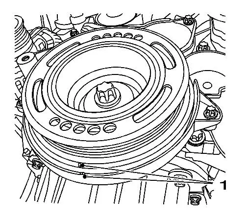
| 2. |
Set the crankshaft balancer in
the direction of the engine rotation to "1st cylinder TDC" (mark
1). |
|
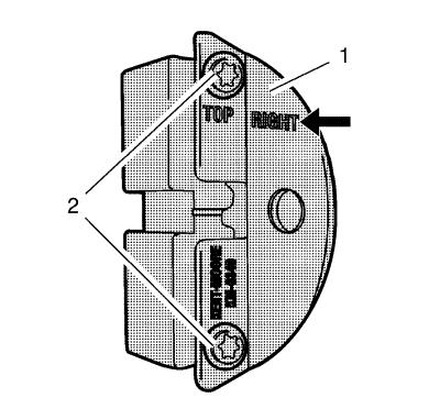
Note: The right half
of the EN-6340 locking tool can be recognised by
the lettering "right", arrow, on the tool.
|
| 4. |
Prepare the right half of the
EN-6340 locking tool . |
| |
4.1 |
Remove the 2 bolts (2).
|
| |
4.2 |
Remove the front panel (1)
from the EN-6340 locking tool -right. |
|
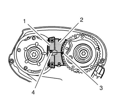
Note:
| • |
The spot type
marking (4) on the intake camshaft position actuator adjuster does
not correspond to the groove of the EN-6340 locking
tool - left (1) during this process, but must be somewhat
above. |
| • |
The spot type
marking (3) on the exhaust camshaft position actuator adjuster must
correspond to the groove on EN-6340 locking tool -
right (2). |
|
| 5. |
Insert the EN-6340
locking tool - left (1) and the EN-6340
locking tool - right (2) in the camshaft position actuator
adjuster. |
|
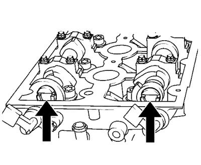
Note: If the
EN-6628-A locking tool cannot be inserted, the
timing must be set.
|
| 6. |
Align the camshafts
horizontally by the hexagon (arrows) until the EN-6628-A
locking tool can be inserted in both camshafts. |
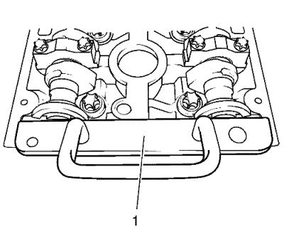
| 7. |
Insert the EN-6628-A
locking tool (1) into the camshafts. |
Installation Procedure
| 1. |
Remove the EN-6628-A
locking tool . |
| 2. |
Remove the EN-6340
locking tool . |
|
