Engine Replacement (Automatic Transmission)
Special Tools
| • |
CH–49290
Engine Support Tool |
| • |
CH–49289
Centering Frame |
For equivalent regional tools, refer to
Special Tools .
Removal Procedure
| 1. |
Position the vehicle on a lift
and remove the key. The wheels should be in the straight-ahead
position and the steering wheel should be locked in a straight
ahead position. |
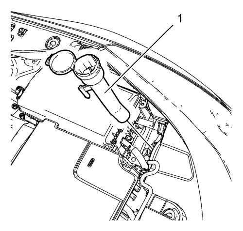
| 8. |
Remove the windshield washer
solvent container filler tube (1). |
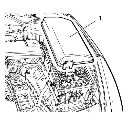
| 9. |
Remove the front compartment
fuse block cover (1). |
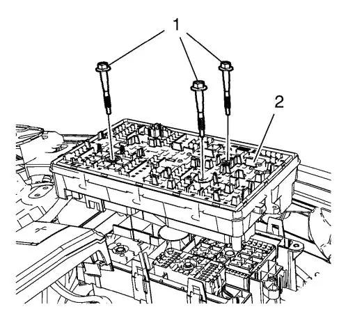
| 10. |
Remove the 3 front compartment
fuse block bolts (1). |
| 11. |
Remove the front compartment
fuse block (2). |
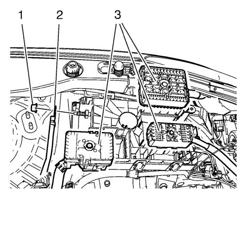
| 12. |
Unclip the 3 wiring harness
plugs (3). |
| 13. |
Disconnect the wiring harness
plug from the front compartment fuse block. |
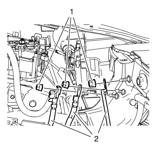
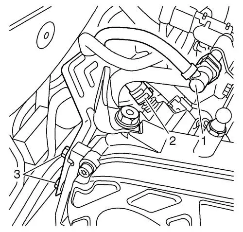
| 14. |
Remove the 3 ground nuts (1)
and put the 4 wiring harness (2) aside. |
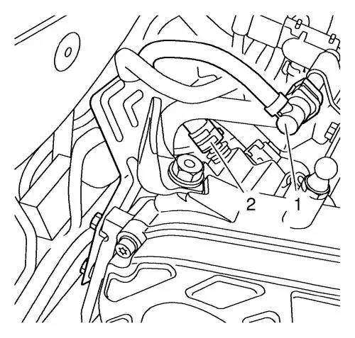
| 15. |
Disconnect the 2 wiring
harness plugs (1, 2). |
| 25. |
Remove the lower and upper
condenser hose nuts and the lower and upper condenser hoses (1,
2). |
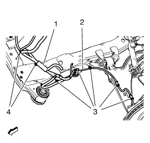
| 30. |
Remove the wheel speed sensor
wiring harness (2) from the frame on both sides. |
| 31. |
Remove the wiring harness
retainers (3) from the frame and the lower control arm.
|
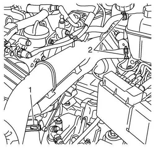
| 32. |
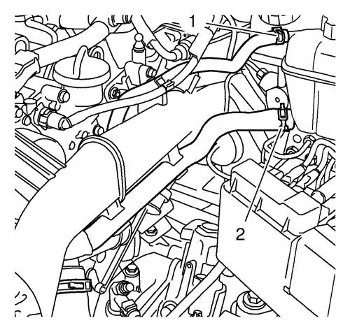
Remove the engine coolant air
bleed hose (1) and the radiator surge tank engine hose (2) from the
surge tank. |
| 33. |
Unclip the transmission vent
hose from the radiator surge tank. |
|
Warning:
Gasoline or gasoline vapors are highly flammable.
A fire could occur if an ignition source is present. Never drain or
store gasoline or diesel fuel in an open container, due to the
possibility of fire or explosion. Have a dry chemical (Class B)
fire extinguisher nearby. |
|
Caution: Clean all fuel pipe connections and surrounding areas
before disconnecting the fuel pipes to avoid contamination of the
fuel system. |
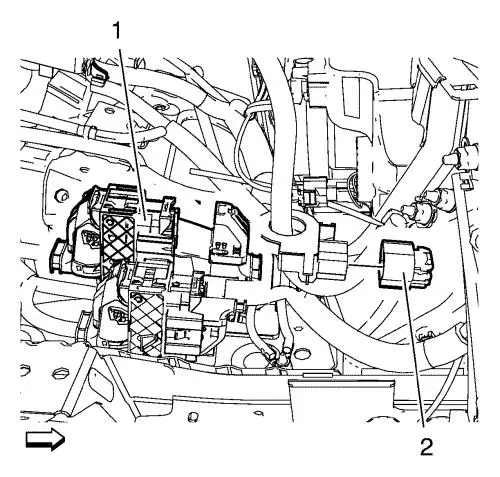
| 36. |
Disconnect the fuel feed pipe
(2) from the fuel pump. |
| 37. |
Disconnect the fuel return
pipe (1). |
| 38. |
Close all connections with
EN-6015 plugs. |
| 40. |
Disconnect the turbocharger
wastegate actuator vacuum control solenoid valve wiring harness
plug. |
| 41. |
Disconnect the negative
pressure pipe from the power brake booster pump. |
| 44. |
Disconnect the 2 wiring
harness plugs from engine cooling fan. |
| 46. |
Install the CH-49290
support tool. For the assembly use attached installation
manual. |
|
Note: The SPX
installation manual is supplied with the special tool and is also
available online from SPX directly. Go to
www.spxtools-shop.com.
|
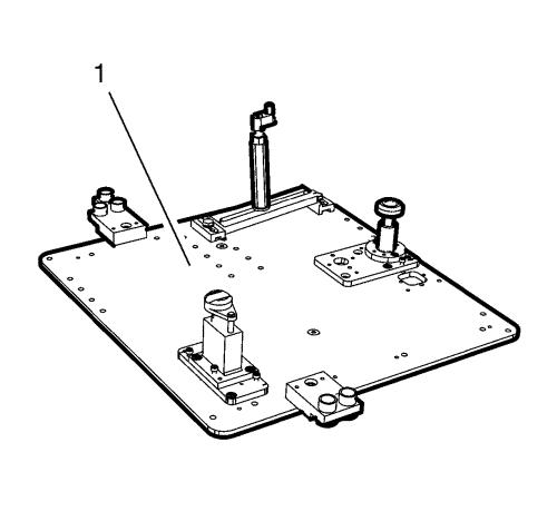
| 49. |
Assemble the CH-49290
support tool (1) according to the details provided in the SPX
installation manual. |
| 50. |
Support the CH-904
base frame on a jack. |
| 51. |
Support the CH-49290
support tool on the CH-904 base frame.
|
|
Note: The SPX
installation manual is supplied with the special tool and is also
available online from SPX directly. Go to
www.spxtools-shop.com.
|
| 52. |
Install the CH-49290
engine support tool (1) according to the details provided in
the SPX installation manual. |
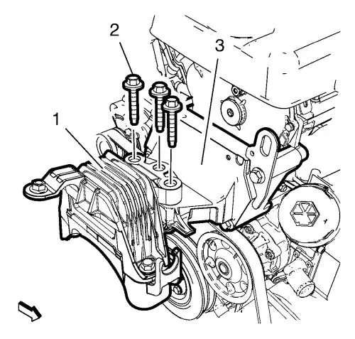
| 53. |
Remove and DISCARD the 3
engine mount bolts (2) from the engine mount (1) and the engine
mount bracket (3). |
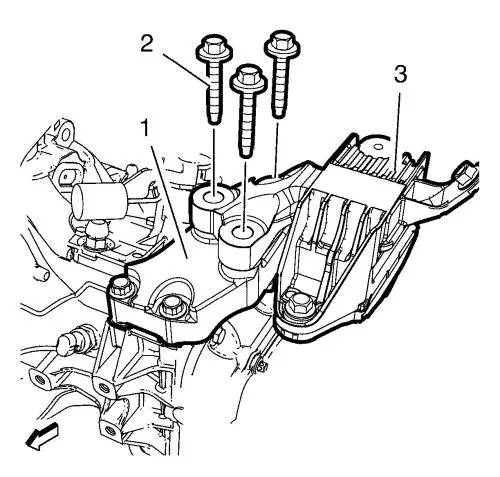
| 54. |
Remove and DISCARD the 3
transmission mount bolts (2) from the transmission mount (3) and
the transmission mount bracket (1). |
|
Note: The SPX
installation manual is supplied with the special tool and is also
available online from SPX directly. Go to
www.spxtools-shop.com.
|
| 55. |
Assemble the CH-49289
centering frame (1) according to the details provided in the
SPX installation manual. |
| 56. |
Support the CH-904
base frame on a jack. |
| 57. |
Support the CH-49289
centring frame on the CH-904 base
frame. |
|
Note: The SPX
installation manual is supplied with the special tool and is also
available online from SPX directly. Go to
www.spxtools-shop.com.
|
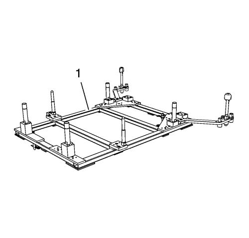
| 58. |
Install the CH-49289
centering frame (1) according to the details provided in the
SPX installation manual. |
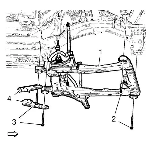
|
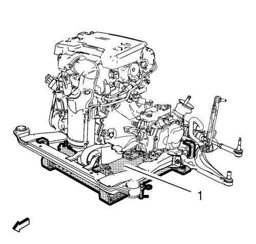
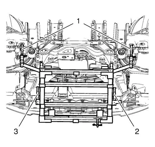
Note: Simplified
graphic. Engine/transmission unit is fixed with engine support tool
to suspension frame. Suspension frame is supported by centering
adapter and underframe.
|
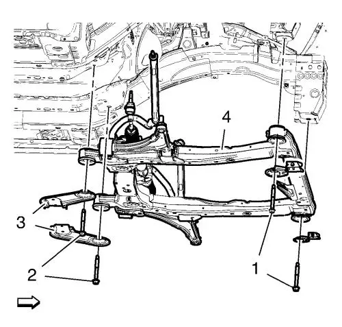
| 59. |
Remove the frame front bolts
(1). |
| 60. |
Remove the frame rear bolts
(2). |
| 61. |
Remove the frame
reinforcements (3). |
| 62. |
Lower suspension frame (4)
carefully with the engine transmission unit off the vehicle with
hydraulic jack about 7 cm (2.76 in) . |
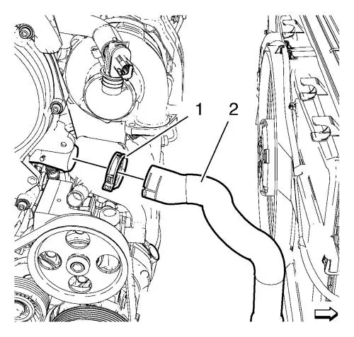
| 66. |
Loosen the radiator outlet
hose clamp (1) and remove the radiator outlet hose (2) from
engine. |
|
Note: Place a basin
underneath to collect any draining transmission fluid.
|
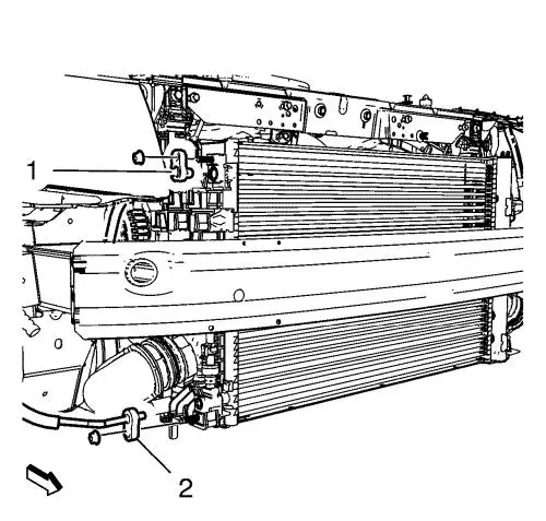
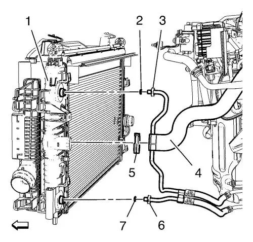
| 67. |
Remove the safety ring and
remove the upper transmission fluid pipe (3) from the radiator
(1). |
| 68. |
Remove the lower safety ring
and remove the lower transmission fluid pipe (6) from the radiator
(1). |
| 69. |
Remove and discard the upper
and lower seal ring (2, 7). |
| 70. |
Remove the cooling module (1)
from the frame. |
| 71. |
Install suitable cable at the
3 engine lift brackets. |
| 72. |
Install a suitable engine
lifting device to the cable. |
| 73. |
Extend the engine lifting
device until the steel cables are slightly tensioned. |
| 76. |
Put the engine transmission
unit down on a wooden pallet. |
|
Note: Second
technician required.
|
| 78. |
Remove the 2 remaining
transmission bolts and the transmission. |
| 79. |
Install the engine to a
suitable engine stand. |
| 80. |
Transfer parts as
needed. |
Installation Procedure
| 1. |
Remove the engine from the
engine stand. |
| 2. |
Put the engine down on a
wooden pallet. |
|
Note: Second
technician required.
|
| 3. |
Install the transmission and
hand tighten 2 transmission bolts. |
| 4. |
Install and hand tighten 6
transmission bolts. |
| 6. |
Place the engine transmission
unit into the front frame. |
| 9. |
Remove the cable from the 3
engine lift brackets. |
| 10. |
Install the cooling module (1)
to the frame and fix it with safety belts. |
| 11. |
Install a New upper
transmission fluid pipe seal ring (2) to the upper fluid pipe
(3). |
| 12. |
Install the upper transmission
fluid pipe (3) to the radiator (1). |
|
Note: Check the
correct hub of the ring and the pipe.
|
| 13. |
Install the safety ring to the
upper transmission fluid pipe and clip in the plastic cover.
|
| 14. |
Install a New lower
transmission fluid pipe seal ring (7) to the lower fluid pipe
(6). |
| 15. |
Install the lower transmission
fluid pipe (6) to the radiator (1). |
|
Note: Check the
correct hub of the ring and the pipe.
|
| 16. |
Install the safety ring to the
lower transmission fluid pipe and clip in the plastic cover.
|
| 17. |
Install the radiator outlet
hose (2) to the engine and tighten the radiator outlet hose clamp
(1). |
| 19. |
Remove the safety belts from
the engine cooling module. |
|
Note: Positioning
pins (1) of CH-49289 adapter MUST be extended in
order to guide into underbody holes.
|
|
Note: Second
technician required.
|
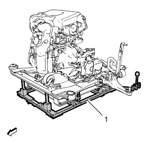
| 23. |
Raise the frame (1) with the
engine transmission unit to the vehicle. |
| 24. |
Install the frame
reinforcements (4) |
| 25. |
Install the 2 front frame
bolts (2). Hand tighten ONLY. |
| 26. |
Install the 2 reinforcement
bolts. Hand tighten ONLY. |
| 27. |
Tighten the rear frame bolts
(3) to 160 N·m (118 lb ft) . |
| 28. |
Tighten the front frame bolts
(2) to 160 N·m (118 lb ft) . |
| 29. |
Lower the CH-49289
centring frame (1) with CH-904 base frame and
a jack. |
| 30. |
Remove the CH-49289
centring frame from the CH-904 base
frame. |
|
Note: The SPX
installation manual is supplied with the special tool and is also
available online from SPX directly. Go to
www.spxtools-shop.com.
|
| 31. |
Disassemble the
CH-49289 centering frame (1) according to the
details provided in the SPX installation manual. |
| 32. |
Install the 3 NEW transmission
mount bolts (2) to the transmission mount (3) and the transmission
mount bracket (1) and tighten in a first pass to 50
N·m (46 lb ft) . |
| 33. |
Tighten the 3 transmission
mount bolts a final pass to an additional 60 - 75
degrees , using the EN–45059
meter. |
| 34. |
Install the 3 NEW engine mount
bolts (2) to the engine mount (1) and the engine mount bracket (3)
and tighten in a first pass to 50 N·m (46 lb
ft) . |
| 35. |
Tighten the engine mount bolts
a final pass to an additional 60 - 75 degrees ,
using the EN–45059 meter. |
| 36. |
Lower the CH-49290
support tool (1) with CH-904 base frame and a
jack. |
| 37. |
Remove the CH-49290
support tool from the CH-904 base
frame. |
|
Note: The SPX
installation manual is supplied with the special tool and is also
available online from SPX directly. Go to
www.spxtools-shop.com.
|
| 38. |
Disassemble the
CH-49290 support tool (1) according to the details
provided in the SPX installation manual. |
| 39. |
Connect the 2 wiring harness
plugs to the engine cooling fan. |
| 42. |
Connect the negative pressure
pipe to the power brake booster pump. |
| 43. |
Connect the turbocharger
wastegate actuator vacuum control solenoid valve wiring harness
plug. |
|
Warning:
Gasoline or gasoline vapors are highly flammable.
A fire could occur if an ignition source is present. Never drain or
store gasoline or diesel fuel in an open container, due to the
possibility of fire or explosion. Have a dry chemical (Class B)
fire extinguisher nearby. |
|
Caution: Clean all fuel pipe connections and surrounding areas
before disconnecting the fuel pipes to avoid contamination of the
fuel system. |
| 45. |
Remove the EN-6015
plugs from all connections. |
| 46. |
Connect the fuel feed pipe (2)
to the fuel pump. |
| 47. |
Connect the fuel return pipe
(1). |
| 50. |
Clip the transmission vent
hose into the radiator surge tank. |
| 51. |
Install the engine coolant air
bleed hose (1) and the radiator surge tank engine hose (2) to the
surge tank. |
| 52. |
Install the wiring harness
retainers (3) to the frame and the lower control arm. |
| 53. |
Install the wheel speed sensor
wiring harness (2) to the frame on both sides. |
| 59. |
Install the lower and upper
condenser hoses (1, 2). |
| 60. |
Install the lower and upper
condenser hose nut and tighten to 19 N·m (14 lb
ft) . |
| 68. |
Connect the 2 wiring harness
plugs (1, 2). |
| 69. |
Instal the 4 wiring harness
(2) and tighten the 3 ground nuts to 9 N·m (80 lb
in) . |
| 70. |
Connect the wiring harness
plugs to the front compartment fuse block. |
| 71. |
Clip in the 3 wiring harness
plugs (3). |
| 72. |
Install the front compartment
fuse block (2). |
| |
Install the 3 front compartment fuse block bolts (1) and
tighten to 22 N·m (16 lb ft) . |
| 73. |
Install the front compartment
fuse block cover (1). |
| 74. |
Remove the windshield washer
solvent container filler tube (1). |
|
