Intake Manifold Replacement
Removal Procedure
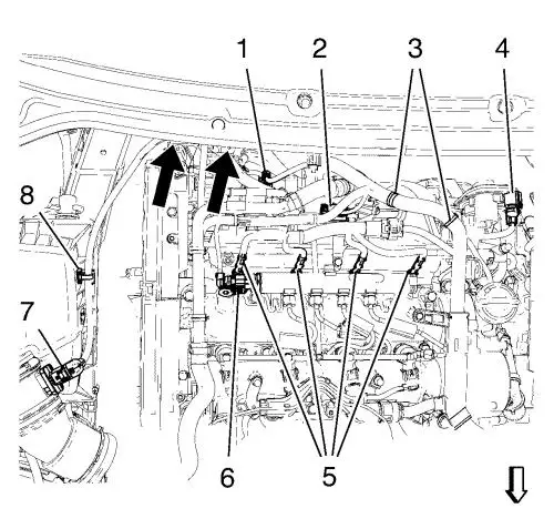
| 6. |
Disconnect the wiring harness
plugs: |
| |
• |
from the air mess sensor
(7). |
| |
• |
from the 4 glow plugs
(5). |
| |
• |
from the fuel rail (6).
|
| |
• |
from the throttle body
(4). |
| |
• |
from the manifold absolute
pressure sensor (2). |
| |
• |
from the fuel injection pump
(1). |
| 7. |
Disconnect the wiring harness
retainer clips: |
| |
• |
from the air filter assembly
(8). |
| |
• |
from the wiring harness
bracket (3). |
| |
• |
from the fuel feed hose
protector (see arrows in picture). |
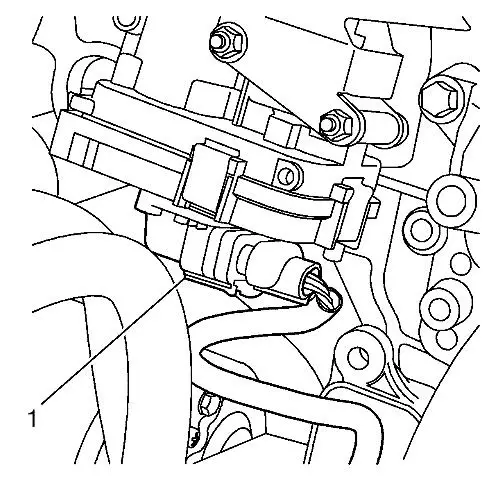
| 10. |
Disconnect the wiring harness
plug (1) from the intake manifold actuator. |
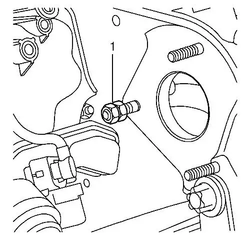
| 13. |
Remove the fuel injection pump
stud (1), use 2 nuts to counter hold. |
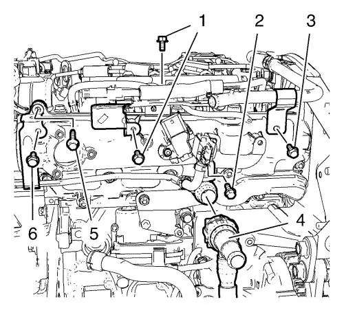
| 14. |
Remove the 2 wiring harness
bracket bolts (1). |
| 15. |
Remove the exhaust pressure
sensor bracket bolt (2). |
| 16. |
Remove the positive crankcase
ventilation tube bolt (3). |
| 17. |
Place a drain tray
underneath. |
| 18. |
Remove the water outlet house
(4) and hang aside. |
| 19. |
Remove the intake manifold
bracket bolt (5). |
| 20. |
Remove the exhaust pressure
sensor pipe bolt (6). |
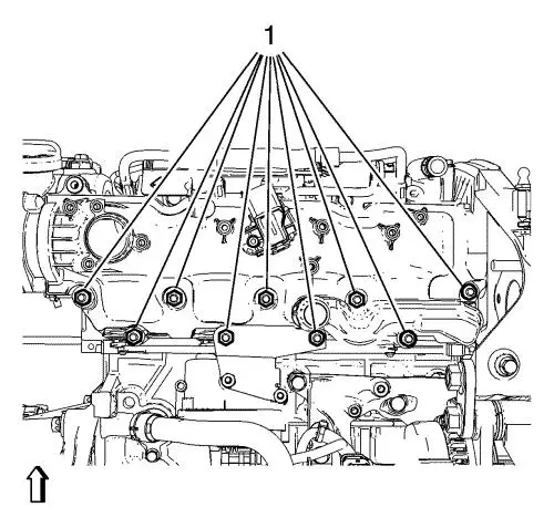
| 21. |
Remove the 9 intake manifold
nuts (1). |
| 22. |
Remove the intake
manifold. |
Installation Procedure
| 1. |
Clean the sealing
surfaces. |
| 2. |
Install a NEW intake manifold
gasket. |
| 3. |
Install the intake
manifold. |
| 4. |
Install the 9 intake manifold
nuts (1) and tighten to 25 N·m (18 lb ft)
. |
| 5. |
Install the wiring harness
bracket bolts (1). |
| 6. |
Install the exhaust pressure
sensor bracket bolt (2). |
| 7. |
Install the positive crankcase
ventilation tube bolt (3). |
| 8. |
Install the water outlet house
(4). |
| 9. |
Install the intake manifold
bracket bolt (5). |
| 10. |
Install the exhaust pressure
sensor pipe bolt (6). |
| 11. |
Install the fuel injection
pump stud (1), use 2 nuts to counter hold. |
| 14. |
Connect the wiring harness
plug (1) to the intake manifold actuator. |
| 16. |
Connect the wiring harness
plugs: |
| |
• |
to the air mess sensor
(7). |
| |
• |
to the 4 glow plugs
(5). |
| |
• |
to the throttle body
(4). |
| |
• |
to the manifold absolute
pressure sensor (2). |
| |
• |
to the fuel injection pump
(1). |
| 17. |
Connect the wiring harness
retainer clips: |
| |
• |
to the air filter assemble
(8). |
| |
• |
to the wiring harness bracket
(3). |
| |
• |
to the fuel feed hose
protector (see arrows in picture). |
|
