Equaliser Beam Link Replacement - Right Side
Special Tools
EN-45059 Angle Sensor Kit
For equivalent regional tools. Refer to
Special Tools .
Removal Procedure
| 3. |
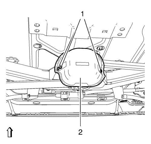
Remove 3 rivets (1) from
equalizer beam center link heat shield (2). |
| 4. |
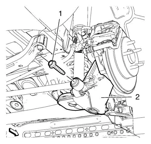
Remove the equalizer beam link
bolt (1) from the rear axle (2). |
| 5. |
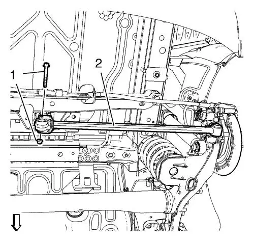
Remove and DISCARD the
equalizer beam link bolt and nut (1) from equalizer beam center
link (2). |
| 6. |
Remove the equalizer beam link
from the vehicle. |
Installation Procedure
| 1. |
Insert equalizer beam link to
the vehicle. |
|
Note: Following step
must be proceed in order to achieve correct rear axle joints
alignment.
|
| 2. |
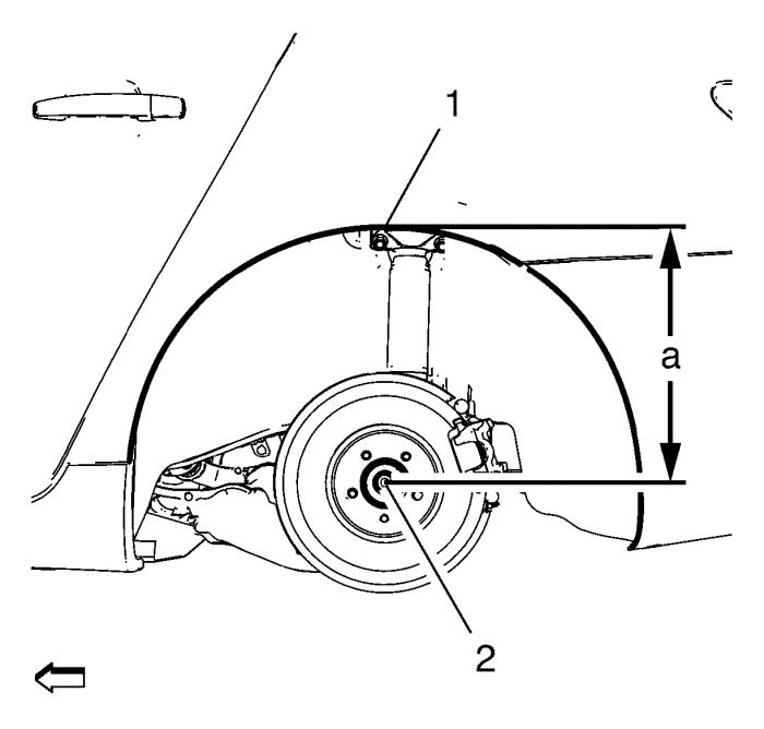
Using the lift table, raise
the axle to the proper trim height specification by measuring the
vertical distance (a) between the center of the wheel hub (2) and
top of the wheel opening (1). |
Specification
Dimension (a): 385 mm
(15.16 in)
| 3. |
Install the NEW equaliser beam
link bolt and nut (1) to equaliser beam centre link (2) and tighten
to 40 N·m (30 lb ft) + 60° , using the
EN-45059 angle meter . |
| 4. |
Install and hand tighten the
equalizer beam link bolt (1) to the rear axle (2) and tighten to
160 N·m (118 lb ft) . |
| 6. |
Lower the vehicle to
ground. |
| 7. |
Install 3 rivets (1) to
equalizer beam center link heat shield (2). |
|
