Electronic Component Description (M36 and MXE)
Transmission Control Module (TCM)
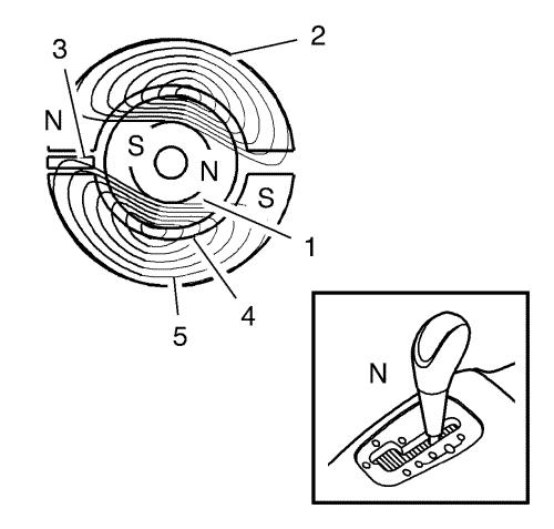
| (1) |
Rotating magnet |
| (2) |
Stator magnet |
| (3) |
IC circuit, Hall sensor |
| (4) |
Coil |
| (5) |
Magnetic field |
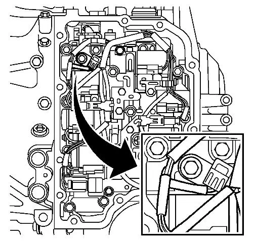
The TCM is mounted directly on top of the transmission. The
selector lever is integrated in the control module. The TCM is
mounted so that the selector lever shaft goes through the control
module. The selector lever position is calibrated with a scan tool,
there is no mechanical adjustment.
An exterior 16-pin connector connects to the car's electrical
system. Underneath the control module is another connector (22-pin)
that connects directly to the transmission. The TCM makes contact
with all the transmission solenoids and sensors here.
Note: Magnetic fields from
e.g. magnets and from high-current cables, such as starter cables
and cables to auxiliary equipment, can interfere with the gear
position sensor. A rule of thumb is max 1A per mm in distance from
the control module. A starter cable carrying a current of 200A must
therefore be kept at least 20 cm away from the control module.
The TCM has a microprocessor with clock, RAM memory and a
programmable ROM. An internal bus connects the processor and memory
with the I/O unit. The I/O unit reads values from the A/D converter
for analogue inputs, digital inputs and bus, as well as activates
the transistors' output stages.
Adaptive values are saved in a non-volatile memory (ROM). When
changing transmission, these values must be zeroed using scan tool.
After changing TCM they will be zeroed automatically after adding
the control module using the scan tool.
Solenoid Valve S1
Overview S1 and S2 Solenoids
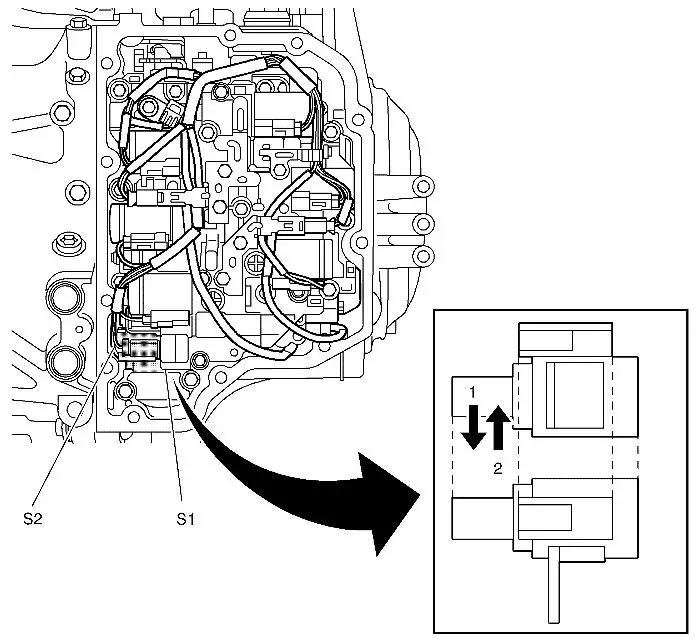
| (1) |
On |
| (2) |
Off |
| (s1) |
Solenoid Valve S1 |
| (s2) |
Solenoid Valve S2 |
The normally open solenoid valve is mounted in the transmission
valve housing and is used by TCM when activating C2. The pressure
to SLC2 is then raised from system pressure to D-pressure. The
valve is also used to apply pressure to brake B2 for engine braking
in 1st gear.
The control module activates the valve by applying B+ to it. The
valve is powered from control module pin 5 in the connector in
direct contact with the transmission on the bottom of the control
module. The valve is grounded in the valve housing.
Solenoid Valve S2
Overview S1 and S2 Solenoids
| (1) |
On |
| (2) |
Off |
| (s1) |
Solenoid Valve S1 |
| (s2) |
Solenoid Valve S2 |
The normally closed solenoid valve is mounted in the
transmission valve housing and is used together with S1 to apply
pressure to brake B2 for engine braking in 1st gear.
The control module activates the valve by applying B+ to it. The
valve is powered from control module pin 2 in the connector in
direct contact with the transmission on the bottom of the control
module. The valve is grounded in the valve housing.
Solenoid Valve SLB1
Overview SLB1, SLC1, SLC2, and SLC3 Solenoids
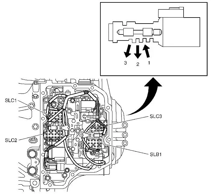
| (1) |
On |
| (2) |
Off |
| (3) |
Ex |
| (slc1) |
Solenoid Valve SLC1 |
| (slc2) |
Solenoid Valve SLC2 |
| (slc3) |
Solenoid Valve SLC3 |
| (slb1) |
Solenoid Valve SLB1 |
The PWM controlled solenoid valve is mounted in the transmission
valve housing and controls the pressure in brake B1. The valve is
active in gear positions P, R, N, D (gears 1, 3, 4 and 5).
The control module activates the valve by pulsing it with B+
(300 Hz PWM). The valve is powered from control module pin 21 in
the connector that makes contact directly with the transmission on
the bottom of the control module. The valve is grounded from pin
16. The current varies between 0-1000mA. The solenoid is normally
open and the hydraulic pressure drops as the current increases.
Solenoid Valve SLC1
Overview SLB1, SLC1, SLC2, and SLC3 Solenoids
| (1) |
On |
| (2) |
Off |
| (3) |
Ex |
| (slc1) |
Solenoid Valve SLC1 |
| (slc2) |
Solenoid Valve SLC2 |
| (slc3) |
Solenoid Valve SLC3 |
| (slb1) |
Solenoid Valve SLB1 |
The PWM controlled solenoid valve is mounted in the transmission
valve housing and controls the pressure in clutch C1. The valve is
active in gear positions P, R, N, D (gears 5 and 6).
The control module activates the valve by pulsing it with B+
(300 Hz PWM). The valve is powered from control module pin 11 in
the connector that makes contact directly with the transmission on
the bottom of the control module. The valve is grounded from pin
10. The current varies between 0-1000 mA. The solenoid is normally
open and the hydraulic pressure drops as the current increases.
Solenoid Valve SLC2
Overview SLB1, SLC1, SLC2, and SLC3 Solenoids
| (1) |
On |
| (2) |
Off |
| (3) |
Ex |
| (slc1) |
Solenoid Valve SLC1 |
| (slc2) |
Solenoid Valve SLC2 |
| (slc3) |
Solenoid Valve SLC3 |
| (slb1) |
Solenoid Valve SLB1 |
The PWM controlled solenoid valve is mounted in the transmission
valve housing and controls the pressure in clutch C2. The valve is
active in gear positions P, R, N, D (gears 1, 2 and 3).
The control module activates the valve by pulsing it with B+
(300 Hz PWM). The valve is powered from control module pin 17 in
the connector that makes contact directly with the transmission on
the bottom of the control module. The valve is grounded from pin
18. The current varies between 0-1000mA. The solenoid is normally
open and the hydraulic pressure drops as the current increases.
Solenoid Valve SLC3
Overview SLB1, SLC1, SLC2, and SLC3 Solenoids
| (1) |
On |
| (2) |
Off |
| (3) |
Ex |
| (slc1) |
Solenoid Valve SLC1 |
| (slc2) |
Solenoid Valve SLC2 |
| (slc3) |
Solenoid Valve SLC3 |
| (slb1) |
Solenoid Valve SLB1 |
The PWM controlled solenoid valve is mounted in the transmission
valve housing and controls the pressure in clutch C3. The valve is
active in gear positions P, N, D (gears 1, 2, 4 and 6).
The control module activates the valve by pulsing it with B+
(300 Hz PWM). The valve is powered from control module pin 14 in
the connector that makes contact directly with the transmission on
the bottom of the control module. The valve is grounded from pin
22. The current varies between 0-1000mA. The solenoid is normally
open and the hydraulic pressure drops as the current increases.
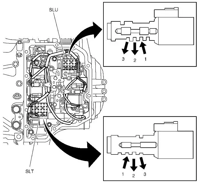
Solenoid Valve SLT
Overview SLT and SLU Solenoids
| (1) |
On |
| (2) |
Off |
| (3) |
Ex |
| (slu) |
Solenoid Valve SLU |
| (slt) |
Solenoid Valve SLT |
The PWM controlled solenoid valve is mounted in the transmission
valve housing and controls the transmission system pressure. The
value is controlled so that it is not higher than what is currently
needed for any friction element. Brake B2 does not have its own
pressure control valve and is therefore supplied by SLT.
The control module activates the valve by pulsing it with B+
(300 Hz PWM). The valve is powered from control module pin 3 in the
connector that makes contact directly with the transmission on the
bottom of the control module. The valve is grounded from pin 1. The
current varies between 0-1000mA. The solenoid is normally open and
the hydraulic pressure drops as the current increases.
Solenoid Valve SLU
Overview SLT and SLU Solenoids
| (1) |
On |
| (2) |
Off |
| (3) |
Ex |
| (slu) |
Solenoid Valve SLU |
| (slt) |
Solenoid Valve SLT |
The solenoid valve is mounted in the transmission valve
housing.
The valve controls the pressure used for the torque converter
clutch. The pressure is modulated so that full, partial or no
engagement is achieved.
The control module activates the valve by pulsing it with B+
(300 Hz PWM). The valve is powered from control module pin 9 in the
connector that makes contact directly with the transmission on the
bottom of the control module. The valve is grounded from pin 4. The
current varies between 0-1000mA. The solenoid is normally closed
and the hydraulic pressure rises as the current increases.
Input Shaft Speed Sensor
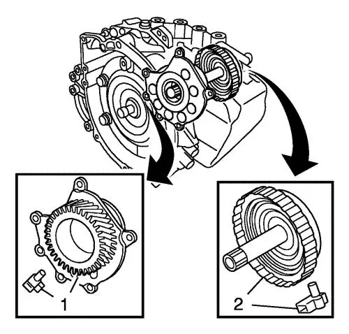
| (1) |
Output shaft gear with output speed sensor |
| (2) |
C2 clutch drum with input speed sensor |
The sensor is mounted inside the valve housing in the front part
of the transmission and measures the speed of the transmission
input shaft. This value is used by TCM to calculate the actual
gearchange time and to regulate lock up. The Hall sensor measures a
toothed wheel with 36 teeth.
The sensor is powered from TCM pin 12 and is grounded through
pin 13.
Output Shaft Speed Sensor
| (1) |
Output shaft gear with output speed sensor |
| (2) |
C2 clutch drum with input speed sensor |
The sensor is mounted inside the valve housing in the rear part
of the transmission and measures the transmission output shaft
speed. This value is used by TCM mainly to determine the gearchange
points. The hall sensor measures a toothed wheel with 56 teeth.
The sensor is powered from TCM pin 19 and is grounded through
pin 20.
Transmission Oil Temperature Sensor
The temperature sensor is mounted in the transmission valve
housing and informs the control module about the current
temperature. The value is used to correct the PWM ratio to the
solenoids so that the gear changes are not affected by the
viscosity of the oil. It is also used to activate the special
gearchange program in case of overheating.
The sensor comprises an NTC resistor built into a plastic
casing. The NTC resistor characteristic means that the resistance
drops as the temperature rises. The NTC resistor is supplied with
5V through a pull up from control module pin 8 and is grounded
through pin 7.
|