Transmission Replacement
Special Tools
| • |
DT-47648
Transmission Holder |
| • |
EN-47649
Engine Support Fixture |
| • |
CH-49290
Engine Support Tool |
For equivalent regional tools, refer to
Special Tools .
Removal Procedure
|
Note: Do NOT
disconnect engine coolant hoses.
|
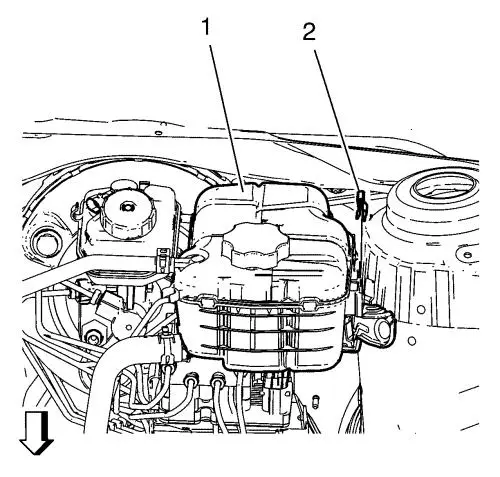
| 2. |
Remove the radiator surge tank
clip (2). |
| 3. |
Remove the radiator surge tank
(1). |
| |
Position the radiator surge tank (1) aside. |
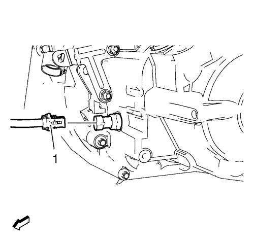
| 5. |
Disconnect backup lamp switch
electrical connector (1). |
|
Note: Before
disconnecting the clutch actuator cylinder front pipe, remove the
clutch/brake fluid from the reservoir tank. Place basin
underneath.
|
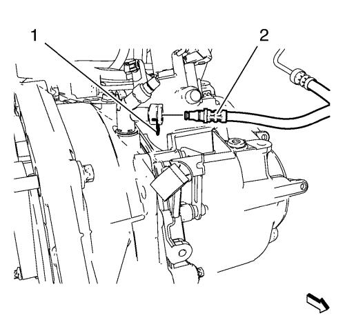
| 6. |
Remove the clutch actuator
cylinder front pipe retainer (1). |
| 7. |
Remove the clutch actuator
cylinder front pipe (2) from the clutch actuator cylinder pipe
elbow. |
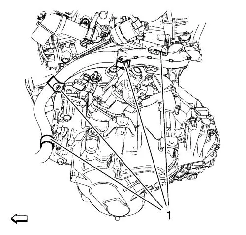
| 8. |
Remove the wiring harness
starter motor from the transmission. Remove the 4 clips (1).
|
| 9. |
Remove the 2 bracket bolts
(2). |
| 10. |
Remove the upper middle wiring
harness starter motor bracket (1). |
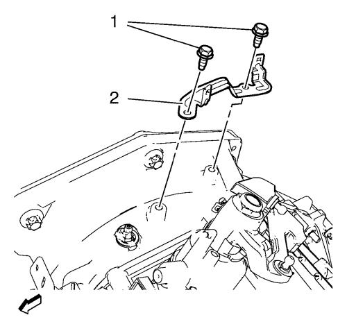
| 11. |
Remove the 2 upper
transmission bolts from engine (1). |
|
Note: The SPX
installation manual is supplied with the special tool and is also
available online from SPX directly. Go to
www.spxtools-shop.com.
|
| 14. |
Assemble the CH-49290
support tool (1) according to the details provided in the
SPX installation manual. |
| 15. |
Support the CH-904
base frame on a jack. |
| 16. |
Support the CH-49290
support tool on the CH-904 base frame
. |
|
Note: The SPX
installation manual is supplied with the special tool and is also
available online from SPX directly. Go to
www.spxtools-shop.com.
|
| 17. |
Install the CH-49290
support tool (1) according to the details provided in the
SPX installation manual. |
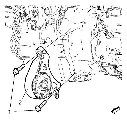
| 19. |
Remove the transmission front
mount from the transmission (2). |
| 20. |
Remove the 2 bolts (1).
|
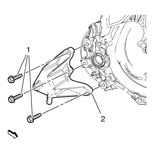
| 21. |
Remove the transmission mount
bracket - rear from the transmission (2). |
| 22. |
Remove the 3 bolts (1).
|
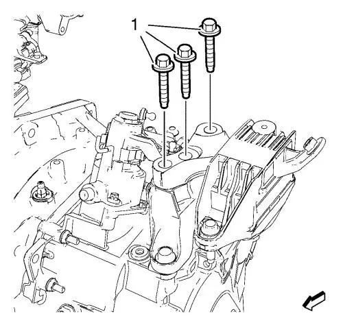
| 28. |
Remove and DISCARD the
transmission left mount bolts (1) from the transmission mount
bracket. |
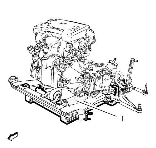
| 29. |
Lower the engine and the
transmission on the left hand side with the EN-47649
engine support fixture . |
| 30. |
Remove the transmission mount
bracket - left side. Remove the 3 transmission mount bracket bolts
(1). |
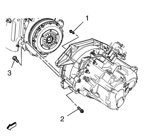
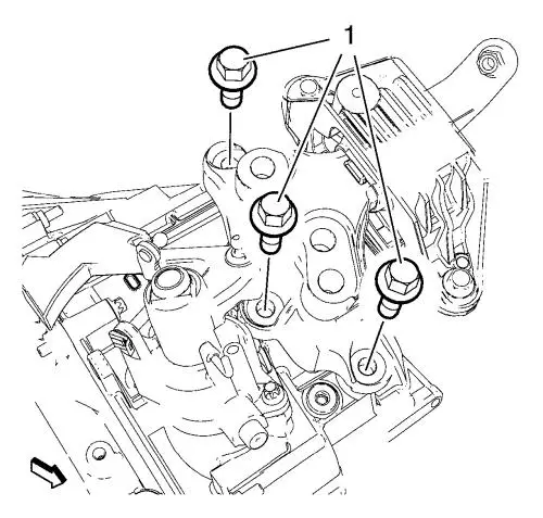
| 33. |
Remove the 3 transmission
lower bolts (1, 2, 3). |
| 34. |
Install the NEW oil drain plug
and tighten to 50 N·m (37 lb ft) .
|
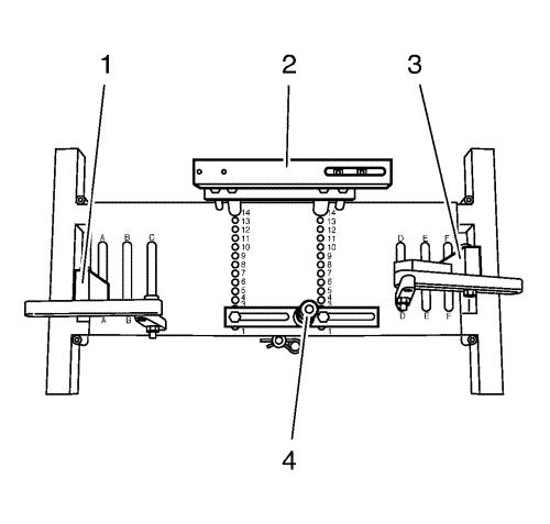
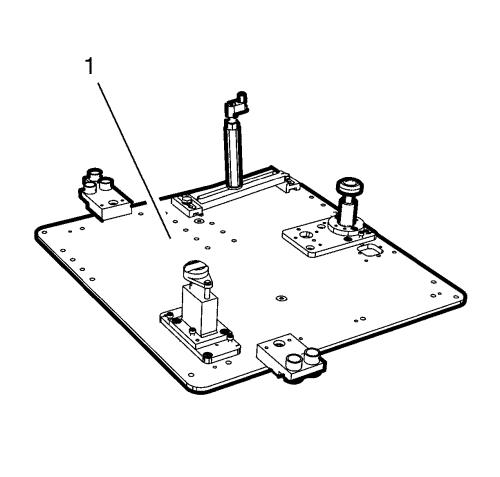
| 35. |
Place the DT-47648
transmission holder on the CH-904 base frame
and pre-install the supports as shown in the illustration.
|
| 36. |
Pre-install the
DT-47648-2 converter housing support (4) to
position 2 on the base plate. |
| 37. |
Pre-install the
DT-47648-3 transmission housing support (2) to
position 14 on the base plate. |
| 38. |
Pre-install the DT-47648-5
left support with rear transmission swivel arm (1) to
position A on the base plate. |
| 39. |
Pre-install the DT-47648-5
right support with front transmission swivel arm (3) to
position F on the base plate. |
|
Note: Before placing
in position slacken all bolt connections of the swivel arms and
supports as far as the base plate. Adjust the supports for the
converter housing and transmission housing using the spindles until
they are as low as possible.
|
| 40. |
Attach the DT-47648
transmission holder to the transmission. |
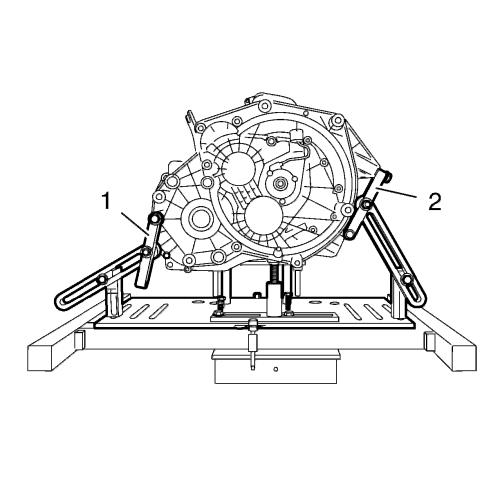
| 41. |
Align DT-47648
transmission holder under transmission. |
| 42. |
Attach the swivel arms (1, 2)
to the transmission. |
|
Note: Align the
swivel arms so that as little leverage as possible is created.
|
| 43. |
Tighten the bolt connections
of the swivel arms, starting from the transmission and going as far
as the base plate. |
| 44. |
Position supports for clutch
housing and transmission housing on transmission by twist up the
spindles. |
| 45. |
Tighten bolt connections of
the supports. |
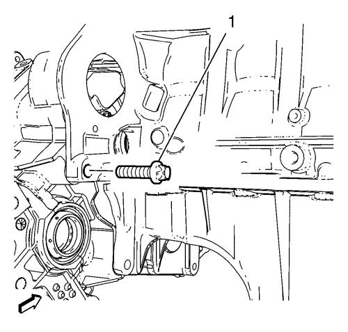
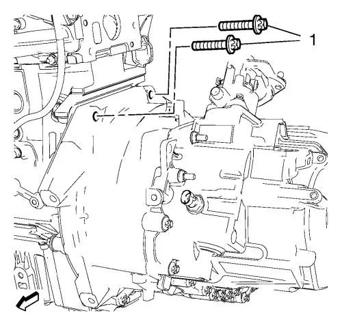
| 46. |
Remove the last transmission
bolt from the engine (1). |
| 47. |
Separate the transmission from
the engine. |
| 48. |
Lower the transmission with
the transmission jack and DT-47648 transmission
holder far enough to remove the transmission. |
Installation Procedure
| 1. |
Raise the transmission with
the transmission jack and DT-47648 transmission
holder and position the transmission to the engine. |
| 2. |
Install the transmission bolt
to the engine (1) and tighten to 60 N·m (44 lb
ft) . |
| 3. |
Remove the transmission jack
with the DT-47648 transmission holder .
|
| 4. |
Install the transmission lower
bolts (1, 2) to the engine and tighten to 40 N·m (30
lb ft) . |
| 5. |
Install the transmission bolt
(3) to the engine and tighten to 60 N·m (44 lb
ft) . |
| 7. |
Install the transmission mount
bracket - left side. Install the 3 transmission mount bracket bolts
(1) and tighten to 100 N·m (74 lb ft)
. |
| 8. |
Raise the engine and the
transmission on the left hand side with the EN-47649
engine support fixture . |
| 9. |
Install the 3 NEW transmission
mount bolts (1) but do not tighten yet. |
| 14. |
Install the transmission mount
bracket - rear (2) and tighten the bolts (1) to 100
N·m (74 lb ft) . |
| 15. |
Install the transmission front
mount to transmission (2). |
| 16. |
Install the 2 transmission
front mount bolts (1) and tighten to 100 N·m (74 lb
ft) . |
| 20. |
Tighten the NEW transmission
mount bolts - left side (1) a first pass to 50 N·m
(37 lb ft) . |
| 21. |
Tighten the NEW transmission
mount bolts - left side (1) a final pass to an additional
60 - 75 degrees . |
| 22. |
Install the upper transmission
to engine bolts (1) and tighten to 60 N·m (44 lb
ft) . |
| 23. |
Lower the CH-49290
support tool (1) with the CH-904 base frame
. |
| 24. |
Remove the CH-49290
support tool from the CH-904 base frame
. |
|
Note: The SPX
installation manual is supplied with the special tool and is also
available online from SPX directly. Go to
www.spxtools-shop.com.
|
| 25. |
Disassemble the
CH-49290 support tool (1) according to the details
provided in the SPX installation manual. |
| 27. |
Install the upper middle
wiring harness starter motor bracket (1). |
| 28. |
Install 2 wiring harness
starter motor bracket bolts (2) and tighten to 22
N·m (16 lb ft) . |
| 29. |
Install the wiring harness
starter motor to the transmission. |
| 30. |
Install the 4 clips
(1). |
| 31. |
Connect the clutch actuator
cylinder front pipe (2) to the clutch actuator cylinder pipe
elbow. |
| 32. |
Install the clutch actuator
cylinder front pipe retainer (1) to the clutch actuator cylinder
pipe elbow. |
| 33. |
Connect the electrical
connector (1) to the backup lamp switch. |
| 36. |
Fill the transmission with
correct fluid. |
| 38. |
Install the radiator surge
tank (1). |
| 39. |
Install the radiator surge
tank clip (2). |
| 41. |
Road test the vehicle.
|
|
