|
Rear Axle, Remove and Install – Models F 08,
F 68 (Cast Link Suspension with Disc Brake)
| Spezialwerkzeugliste: |
- KM-6180-1
- KM-6180-2
- KM-904
- MKM-558-10
|
 Remove Remove
| 1. |
For Tigra-B (model R97): remove left and right torsion struts
|
| 2. |
Position vehicle on lifting platform
|
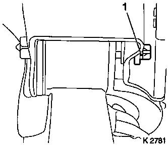
| 3. |
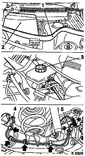
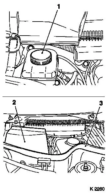
Lift off seal (1) on plenum chamber as far as necessary.
|
| 4. |
Raise covering cap (2) of main brake cylinder
|
| 5. |
Detach cover (3) of brake fluid reservoir
|
| 6. |
Remove rear wheels
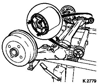
Note: Mark position
relative to wheel hub.
| • |
Disconnect wiring harness plug for ABS (5) on both sides
|
| • |
Unclip wiring harness plug for ABS (5) from brake lines
(arrows)
|
| • |
Unclip wiring harness plug for ABS (5) from bracket on rear
axle (4)
|
|
|
|
| 7. |
Detach linkage for headlamp range control sensor from bracket
on rear axle
Note: For vehicles with
Xenon headlights
|
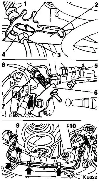
| 8. |
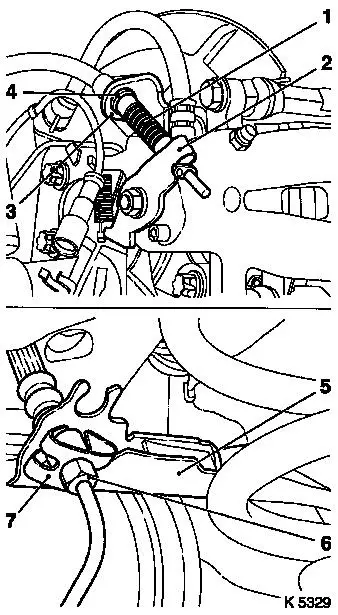
Detach rear parking brake cable (1) out of lever for parking
brake (2) on both sides
|
| 9. |
Detach retaining plate (4) for parking brake cable on both
sides from counterhold (3)
|
| 10. |
Remove parking brake cable out of counterhold and guide on rear
axle (5)
|
| 11. |
Detach rear brake line (6) from rear brake hose on both sides
of rear axle
|
| 12. |
Remove brake hose from bracket
| • |
Retaining plate (7) remains on brake line
|
|
|
|
Important: The rear springs can
only be removed and installed consecutively for each vehicle
side.
|
| 13. |
Remove rear springs - proceed as follows
Note: In the following,
the removal and installation for one side is described. The
operations on the other side are performed analogously.
|
| 14. |
Support rear axle at the trailing link with hydraulic jack on
the side to be fitted
|
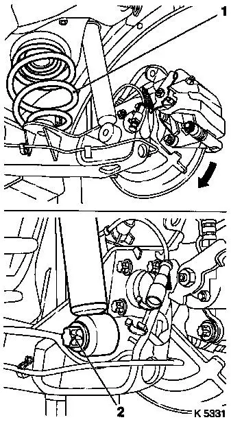
| 15. |
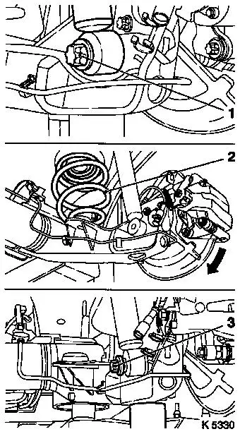
Remove fastening bolt for shock absorber (1) on rear axle.
|
| 16. |
Lower hydraulic jack slowly and remove
|
| 17. |
Pull rear axle downwards on the side to be fitted (arrow)
| • |
until the rear spring (2) can be removed
Note: Note installation
position of spring.
|
|
| 18. |
Position hydraulic jack on trailing link of rear axle.
|
| 19. |
Lift rear axle with hydraulic jack far enough to enable the
shock absorber to be fitted
|
| 20. |
Attach shock absorbers to rear axle
| • |
with fastening bolt (3)
|
|
|
|
| 21. |
Remove rear spring on the other side
Note: Removal takes
place in the same way.
|
| 22. |
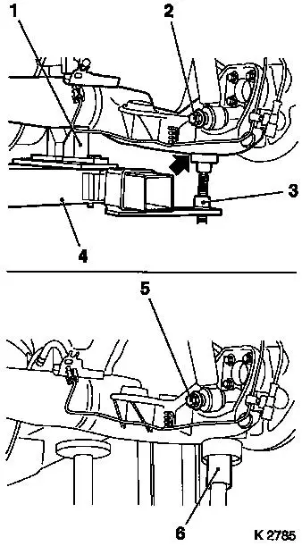
Place hydraulic jack under rear axle
| • |
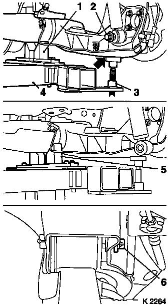
with KM-904 (4), KM-6180-2 (3) and KM-6180-1
(1)
Note: Ensure that the
guide bolt (arrow) of KM-6180-2 is seated
correctly on both sides in the guide hole in the rear axle.
|
|
| 23. |
Detach fastening bolt (2) for shock absorber on both sides.
|
| 24. |
Lift rear axle with the hydraulic jack until the rear axle lies
on KM-6180-1 (5)
|
| 25. |
Detach fastening bolt (6) for trailing link of the rear axle
from vehicle underbody
|
|
|
| 26. |
Lower rear axle slowly with hydraulic jack and remove
Note: When replacing
the rear axle body, all the attaching parts must be refitted on the
new part
|
| 27. |
Clean outer flanks of the damping bushing and - see "Technical
Data"
| • |
Grease with red grease in the marked areas 
Note: Illustration
shows cast link suspension with drum brake.
|
|
|
|
 Install
| 28. |
Bring rear axle slowly towards vehicle underbody
| • |
with hydraulic jack, KM-904 , KM-6180-1 and KM-6180-2
|
|
| 29. |
Attach trailing link of rear axle on both sides to vehicle
underbody
| • |
with new fastening bolts and nuts (1)
| – |
Only screw fastening bolts on loosely
|
|
|
|
|
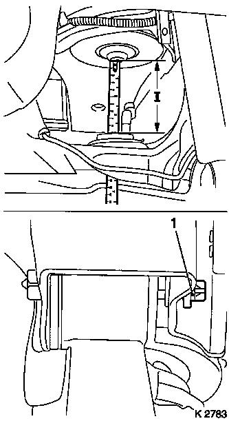
Important: To prevent distortion
of the damping bushings in the trailing link of the rear axle on
the vehicle underbody while driving, the rear axle must be adjusted
to the dimension (I) before tightening the fastening bolts to
torque.
|
| 30. |
Raise rear axle
Note: To measure, place
measuring stick against spring mount through opening in rear
axle.
| • |
with hydraulic jack, KM-904 and KM-6180-2
| – |
Measurement (I): 100 mm ± 5
mm between spring mounting on the rear axle and rear of side
member (see illustration)
|
|
|
| 31. |
Tighten fastening bolts (1), rear axle, on vehicle underbody on
both sides
| • |
Tightening torque 50 Nm + 45° +
15°
|
|
|
|
| 32. |
Position rear axle in such a way that both shock absorbers can
be fitted on the rear axle
| • |
with hydraulic jack, KM-904 (4),
KM-6180-2 (3) and KM-6180-1 (1)
|
|
| 33. |
Attach shock absorbers on both sides of rear axle
| • |
with fastening bolt (2)
|
|
| 34. |
Remove hydraulic jack
| • |
with KM-904 , KM-6180-1 and KM-6180-2
|
|
| 35. |
Install rear springs - proceed as follows.
Note: The rear springs
may only be installed individually, on each vehicle side.
|
| 36. |
Support rear axle at the trailing link with hydraulic jack (6)
on the side to be fitted
|
| 37. |
Remove fastening bolt for shock absorber (5) on rear axle
|
|
|
| 38. |
Lower hydraulic jack slowly and remove
|
| 39. |
Pull rear axle downwards on the side to be fitted (arrow)
| • |
until rear spring (1) can be inserted
|
|
| 40. |
Position hydraulic jack on trailing link of rear axle.
|
| 41. |
Raise rear axle with hydraulic jack
| • |
until shock absorber can be installed on rear axle
|
|
| 42. |
Attach shock absorbers to rear axle
| • |
with fastening bolt (2)
| – |
Tightening torque 110 Nm
|
|
|
| 43. |
Install rear spring on the other side
Note: Installation
takes place in the same way.
|
|
|
| 44. |
Insert brake hose (1) on both sides in bracket on rear axle
body
| • |
Attach brake line (3) with retaining plate (4) on brake
hose
| – |
Tightening torque 16 Nm
|
|
|
| 45. |
Insert rear parking brake cable on both sides in the guide (2)
on the rear axle and counterhold (7) on the brake calliper
|
| 46. |
Suspend parking brake cable (5) on the lever for the parking
brake (6)
|
| 47. |
Attach retaining plate (8) for parking brake cable on
counterhold on brake calliper
|
| 48. |
Clip ABS wiring harness into bracket (9) on rear axle body and
on the brake line (arrows)
| • |
Connect ABS wiring harness (10) electrically
|
|
| 49. |
Attach linkage for headlamp range control sensor to bracket on
rear axle
Note: For vehicles with
Xenon headlights
|
|
|
| 50. |
Attach rear wheels
| • |
Tightening torque 110 Nm
|
|
| 51. |
Remove MKM-558-10 (1) from brake
fluid reservoir.
|
| 52. |
Bleed brake system and check for leaks
|
| 53. |
Seal brake fluid reservoir with sealing cover
|
| 54. |
Fold down covering cap (2) for brake fluid reservoir
|
| 55. |
Place seal (3) on plenum chamber
|
|
|
| 56. |
For Tigra-B (model R97): install left and right torsion struts
|
|
