|
J609100 Coolant Pump, Remove and Install (Z 18 XE,
with Air Conditioning, LHD)
Note: KM-6394 must be used as of model year 04 instead of
KM-6169-1 .
 Remove Remove
| 2. |
Disconnect battery
Note: In vehicles from
model year 04 onwards with ESP - the steering angle sensor loses
its basic adjustment each time the battery is disconnected and must
be recalibrated.
|
| 3. |
Remove engine cover.
| • |
Unscrew oil filler pipe cap
|
| • |
Screw on oil filler pipe cap
|
|
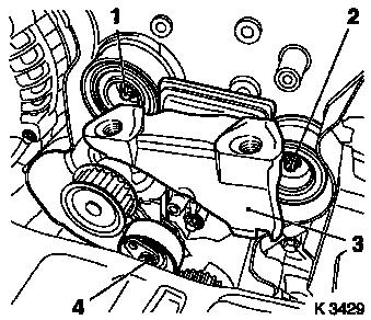
| 4. |
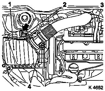
Remove air cleaner housing (1)
| • |
Disconnect 2 wiring harness plugs
| – |
Hot film mass air flow meter (4), tank vent valve (2)
|
|
| • |
Detach engine vent hose (3)
|
|
|
|
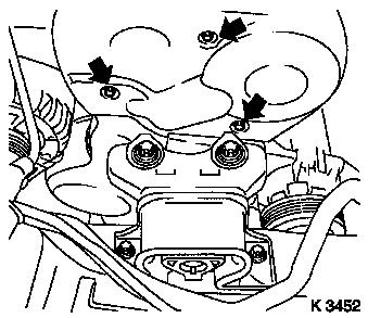
| 5. |
Remove upper part of toothed belt cover
| • |
Unscrew 3 bolts (arrows)
|
| • |
Unclip from rear toothed belt cover
|
|
|
|
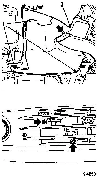
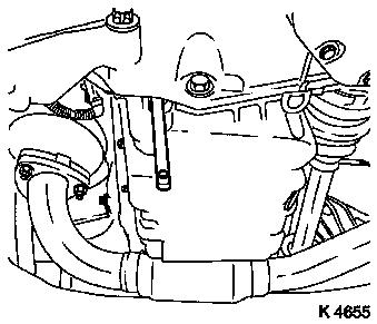
| 7. |
Remove right-hand air duct
| • |
Unscrew 3 bolts (arrows)
|
|
| 8. |
Remove ribbed V-belt cover
|
|
|
| 10. |
Detach front right wheel
|
| 12. |
Remove right front wheel.
|
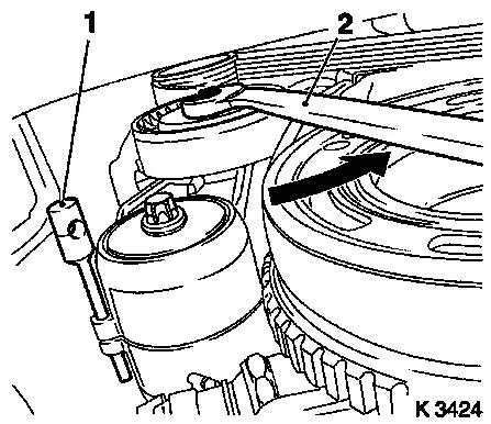
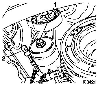
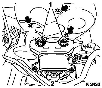
| 14. |
Remove ribbed V-belt
| • |
Tension ribbed V-belt tensioner in direction of arrow with
KM-913-A (2)
|
|
|
|
| 15. |
Remove ribbed V-belt tensioner
| • |
Tension ribbed V-belt tensioner.
|
| • |
Release ribbed V-belt tensioner
|
|
|
|
| 16. |
Detach crankshaft ribbed V-belt pulley
| • |
Prise front closure plug out of oil pan
|
|
|
|
| 17. |
Release lower part of toothed belt cover
| • |
Unclip from rear toothed belt cover
|
|
|
|
| 19. |
Remove lower part of toothed belt cover
| • |
Unclip from rear toothed belt cover
|
|
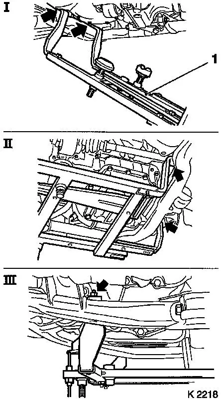
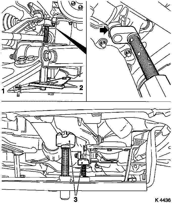
| 20. |
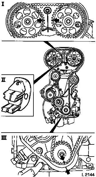
Attach KM-6169 (1)
| • |
Attach KM-6169 to left of front axle
body (arrows, illus. I)
| – |
Guide pin must be seated in bore in front axle body
|
|
| • |
Attach both right holders on the front axle body (arrows,
Illus. II).
| – |
Guide pin must be seated in bore in front axle body (arrow,
Fig. III)
|
|
|
|
|
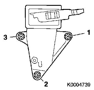
| 21. |
Install support
| • |
An KM-6169
| – |
Adjust bracket (2) for support
|
|
|
| 22. |
Adjust supports
| • |
Transmission side
| – |
Turn spindles until mounts (3) are positioned at guide journals
free of play
|
|
| • |
Engine timing side
| – |
Insert journal of the support in the bore of the cylinder block
without play (arrow)
|
|
|
|
|
| 24. |
Remove right engine damping block
| • |
Loosen engine bracket adapter
|
| • |
Loosen engine damping block
|
|
| 25. |
Remove upper part of toothed belt cover
| • |
Unscrew 3 bolts (arrows)
|
| • |
Unclip from rear toothed belt cover
|
|
| 26. |
Disconnect camshaft sensor wiring harness plug
|
| 27. |
Remove lower part of toothed belt cover
| • |
Unclip from rear toothed belt cover
|
|
|
|
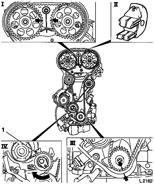
| 28. |
Set 1st cylinder to TDC of combustion stroke
| • |
Install crankshaft V-belt pulley bolt
|
| • |
Set crankshaft to mark.
| – |
Marks on drive gear toothed belt and rear toothed belt cover
must align (III).
|
|
| • |
Fix camshaft sprockets in position.
| – |
Marks must be opposite one another and aligned with the top
edge of the cylinder head (I)
|
|
|
| 29. |
Remove toothed belt
| • |
Release toothed belt tension roller (IV)
| – |
Turn adjusting eccentric in direction of arrow (clockwise)
until pointer (1) of the toothed belt tension roller is located
just before left stop.
|
|
|
|
|
| 31. |
Remove toothed belt drive pulley
| • |
Unscrew crankshaft ribbed V-belt pulley bolt
|
|
|
|
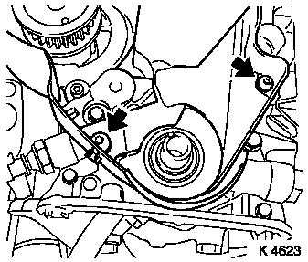
| 32. |
Release rear toothed belt cover
| • |
Unscrew 2 bolts (arrows)
|
|
|
|
| 33. |
Remove intake side toothed belt guide roller
|
| 34. |
Remove exhaust side toothed belt guide roller
|
| 35. |
Remove right engine bracket (3)
|
| 36. |
Remove toothed belt tension roller
|
|
|
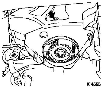
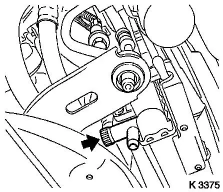
| 38. |
Drain coolant
| • |
Place collecting basin underneath.
|
| • |
Open drain bolt (arrow)
|
|
|
|
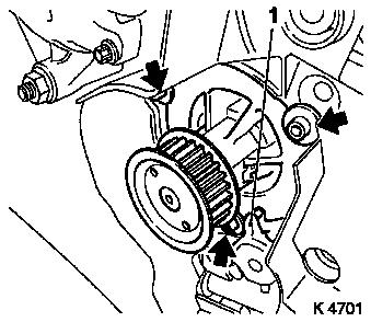
| 40. |
Remove coolant pump
| • |
Unscrew 3 bolts (arrows)
|
|
|
|
 Install
| 41. |
Clean cylinder block sealing surfaces
|
| 42. |
Inspect components
| • |
Ribbed V-belt, ribbed V-belt tensioner, ribbed V-belt pulleys,
toothed belt drive
|
|
| 43. |
Install coolant pump
| • |
Coat sealing surface with silicone grease
|
| • |
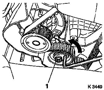
Carefully prise off rear toothed belt cover
Note: Ensure that the
lug of the oil pump (1) engages in the groove of the coolant
pump
|
|
| 45. |
Fasten rear toothed belt cover
|
| 46. |
Install toothed belt drive gear
| • |
Install crankshaft V-belt pulley bolt
|
|
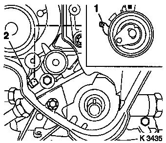
| 48. |
Install toothed belt tension roller
| • |
Detent lever (1) of toothed belt tension roller must engage in
guide web (2) of oil pump.
|
| • |
Bolt in bolt
Note: Adjust toothed
belt tension before tightening bolt.
|
|
|
|
| 49. |
Install right engine bracket
| • |
Insert bolts with locking compound (red)
|
| • |
Tighten 3x bolts 65 Nm + 45° -
60°
|
|
|
|
| 50. |
Install intake side toothed belt guide roller
Note: The toothed belt
guide roller with the greater diameter is installed at the intake
side.
|
| 51. |
Install exhaust side toothed belt guide roller
|
| 52. |
Fix camshaft sprockets in position.
| • |
Marks must be opposite one another and aligned with the top
edge of the cylinder head (I)
|
| • |
Use KM-852 (II)
| – |
Turn the camshafts at hexagonal section
|
|
|
| 53. |
Lock crankshaft
| • |
Set crankshaft to mark.
| – |
Marks on drive gear toothed belt and rear toothed belt cover
must align (III).
|
|
|
|
|
| 54. |
Inspect components
| • |
Ribbed V-belt, ribbed V-belt tensioner, ribbed V-belt pulleys,
toothed belt drive
|
|
| 55. |
Install toothed belt
Note: Pay attention to
direction of travel and timing marks.
| • |
Position toothed belt
| – |
Tensioned side must be taut.
|
|
|
| 56. |
Tension toothed belt
| • |
Tension toothed belt tension roller
| – |
Turn adjusting eccentric in direction of arrow (anticlockwise)
until pointer of the toothed belt tension roller is located just
before left stop
|
|
| • |
Fasten toothed belt tension roller bolt (1)
|
|
|
|
| 58. |
Timing, Check
| • |
Turn crankshaft in direction of engine rotation at the
crankshaft ribbed V-belt pulley bolt (720°)
|
| • |
Set crankshaft to mark.
| – |
Marks on drive gear toothed belt and rear toothed belt cover
must align (III).
|
|
| • |
Use KM-852 (II)
| – |
Marks must be opposite one another and aligned with the top
edge of the cylinder head (I)
|
|
|
|
|
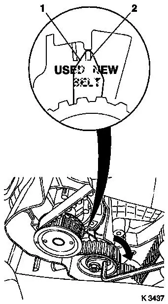
| 60. |
Adjust toothed belt tension
| • |
Release toothed belt tension roller
|
| • |
Turn adjustment eccentric in the direction of the arrow
(clockwise) until pointer (1) of toothed belt tension roller is
aligned with the notch mark NEW (2).
|
| • |
Tighten toothed belt tension roller bolt 20 Nm
|
|
| 61. |
Check toothed belt tension
| • |
Pointer on the toothed belt tension roller and notch mark NEW
must align
|
|
|
|
| 62. |
Install lower part of toothed belt cover
| • |
Clip to rear of toothed belt cover
|
|
| 63. |
Install upper part of toothed belt cover
| • |
Clip to rear toothed belt cover
|
|
| 64. |
Connect camshaft sensor wiring harness plug
| • |
Connect wiring harness plug
|
|
| 65. |
Install right engine damping block
| • |
Fasten engine bracket adapter
| – |
Tighten 2x bolts 60 Nm + 30° -
45°
|
|
| • |
Fasten engine damping block
|
|
| 69. |
Install ribbed V-belt tensioner
| • |
Tension ribbed V-belt tensioner with KM-913-A
|
|
| 70. |
Attach crankshaft ribbed V-belt pulley
| • |
Tighten bolt 95 Nm + 30° +
15°
|
| • |
Insert front closure plug
|
|
| 71. |
Install ribbed V-belt
Note: Observe running
direction and installation position
| • |
Slacken ribbed V-belt tensioner with KM-913-A
|
|
| 72. |
Install ribbed V-belt cover
|
| 73. |
Install right-hand air duct
|
| 75. |
Attach front right wheel
|
| 77. |
Fasten right front wheel.
|
| 78. |
Install air cleaner housing
| • |
Attach engine vent hose
|
| • |
Clip in tank vent valve
|
| • |
Connect 2 wiring harness plugs
|
|
| 79. |
Install engine cover.
| • |
Unscrew oil filler pipe cap
|
| • |
Screw on oil filler pipe cap
|
|
| 81. |
Calibrate steering angle sensor
| • |
Rotate the steering wheel one time from its right-hand to its
left-hand stop
|
|
| 82. |
Program volatile memories
|
|
