|
J609100 remove and install coolant pump (Z 14 XE,
Z 16 YNG with AC, RHD)
Note: KM-6394 must be used as of model year 04 instead of
KM-6169-1 .
|
1. Open bonnet
Important: On
vehicles as of model year 04 with ESP - the steering angle sensor
loses its basic adjustment each time the battery is disconnected.
It must be recalibrated.
2. Disconnect battery
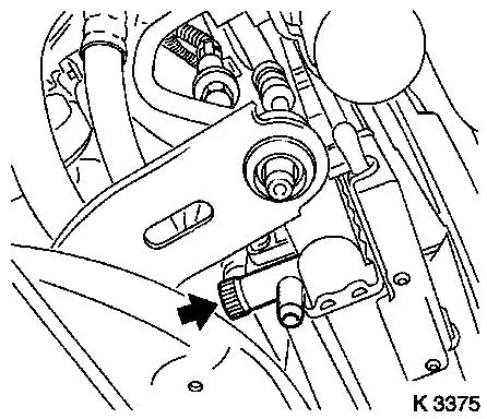
3. Drain coolant
- Place collecting basin underneath.
- Open drain bolt (arrow)
|
|
|
4. Remove engine cover
- Unscrew oil filler pipe cap
- Remove 2 bolts
- Screw on oil filler pipe cap
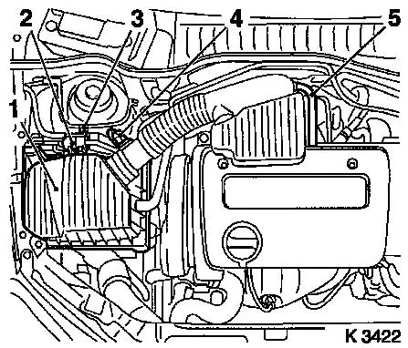
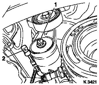
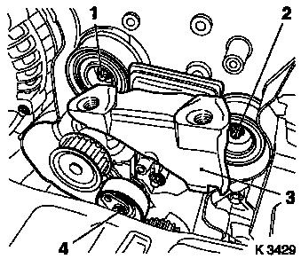
5. Remove air cleaner housing (1)
- Disconnect wiring harness plug
- Intake air temperature sensor (4), tank vent valve (2)
- Unclip tank vent valve
- Remove air intake pipe
- From throttle valve module
- Detach engine vent hose (5)
- Remove air intake hose
- Remove bolt (3)
|
|
|
6. Loosen right front wheel
7. Raise vehicle
8. Remove right front wheel
9. Raise vehicle
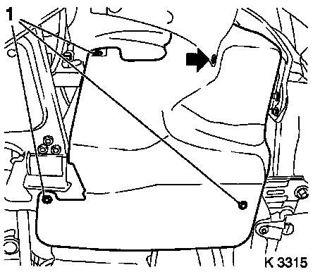
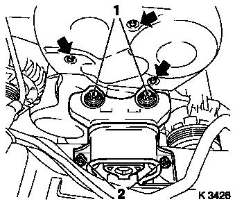
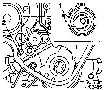
10. Remove ribbed V-belt cover
- Remove 3 bolts (1)
- Remove clip (arrow).
|
|
|
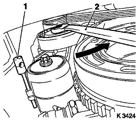
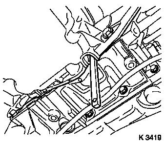
11. Remove ribbed V-belt
- Tension ribbed V-belt tensioner in direction of arrow
- With KM-913-A (2) (SW 15)
- Insert KM-6130 (1)
- Note: Mark running direction
|
|
|
12. Remove ribbed V-belt tensioner
- Tension ribbed V-belt tensioner.
- Remove KM-6130 (2)
- Release ribbed V-belt tensioner
- Remove bolt (1)
|
|
|
13. Detach crankshaft ribbed V-belt
pulley
- Lever out front closure plug
- Insert KM-911
- Remove bolt
- Remove KM-911
|
|
|
14. Loosen lower part of toothed belt
cover
- Remove bolt (arrow)
- Unclip from rear toothed belt cover
|
|
|
15. Attach KM-6169-3
- Tighten bolts (95 Nm / 70 lbf. ft.)
|
|
|
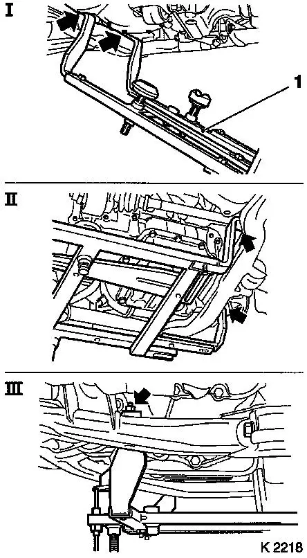
16. Attach KM-6169 (1)
- Place left of KM-6169 onto front axle body (arrows, illus.
I)
- Note: Guide pin must be seated in bore in front axle body
- Attach both right holders on the front axle body (arrows,
Illus. II).
- Note: Guide pin must be seated in bore in front axle body
(arrow, Illus. III)
- Tighten bolts
|
|
|
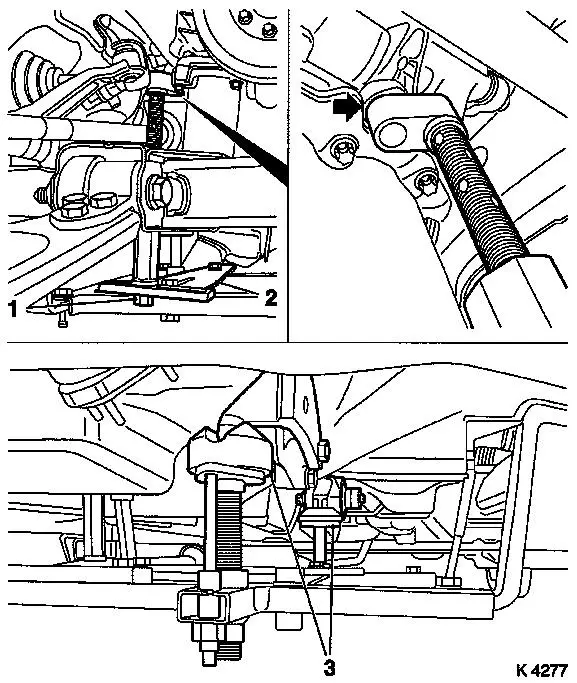
17. Install support
- To KM-6169
- Adjust bracket (2) for support
- Screw on nut (1)
18. Adjust supports
- Transmission side
- Note: Turn spindles until the mounts (3) are positioned at the
guide journals free of play
- Engine timing side
- Insert journal of the support in the bore of the cylinder block
without play (arrow)
- Tighten nuts (1)
19. Lower vehicle
|
|
|
20. Remove right engine damping block
- Loosen engine bracket adapter
- Loosen engine damping block
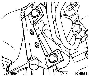
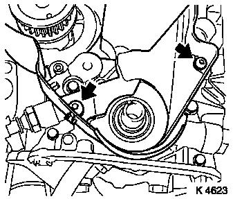
21. Remove upper part of toothed belt cover
- Remove 3 bolts (arrows)
- Unclip from rear toothed belt cover
22. Remove lower part of toothed belt cover
- Unclip from rear toothed belt cover
23. Disconnect wiring harness plug for camshaft sensor
|
|
|
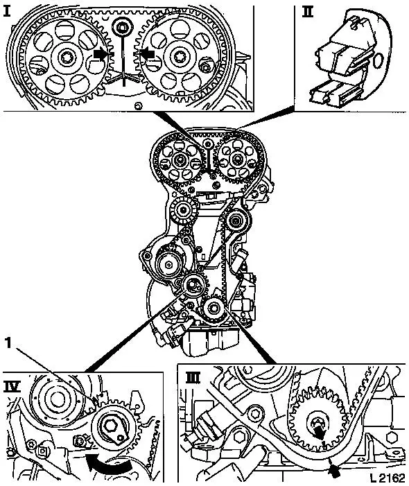
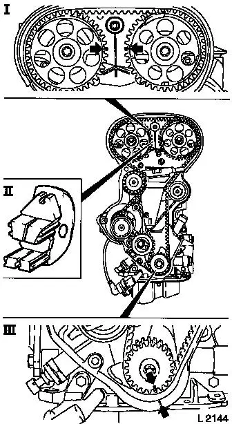
24. Set 1st cylinder to TDC
- Install crankshaft V-belt pulley bolt
- Set crankshaft to mark.
- Turn crankshaft evenly
- Note: Marks on drive gear toothed belt and rear toothed belt
cover must align (III)
- Lock camshafts
- Note: Marks must be opposite one another and aligned with the
top edge of the cylinder head (I)
- Insert KM-852 (II)
25. Remove toothed belt
- Release toothed belt tension roller (IV)
- Loosen bolt
- Turn adjusting eccentric in direction of arrow (clockwise)
until pointer (1) of the toothed belt tension roller is located
just before left stop.
- Note: Mark running direction
- Remove toothed belt.
|
|
|
26. Remove intake side toothed belt guide roller
27. Remove exhaust side toothed belt guide roller
28. Remove right engine bracket (3)
29. Remove toothed belt tension roller
30. Raise vehicle
|
|
|
31. Remove toothed belt drive gear
- Hold with KM-911
- Unscrew crankshaft ribbed V-belt pulley bolt
- Remove toothed belt drive pulley
32. Loosen rear toothed belt cover
33. Lower vehicle
|
|
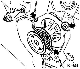
34. Remove coolant pump
|
35. Clean sealing surfaces
|
|
|
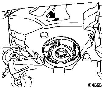
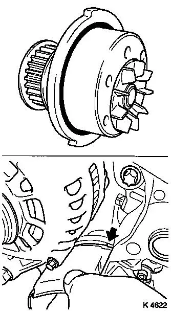
36. Install coolant pump
- Coat sealing surface with silicone grease
- Replace seal ring
- Note: Carefully lever off rear toothed belt cover. Mark on
cylinder block must be aligned with mark on coolant pump
(arrow)
- Tighten bolts (8 Nm / 6 lbf. ft.)
37. Raise vehicle.
38. Fasten rear of toothed belt cover
- Tighten bolts (6 Nm / 4.4 lbf. ft.)
39. Insert toothed belt drive gear in place
40. Lower vehicle
|
|
|
41. Install toothed belt tension roller
- Caution: Detent lever (1) of toothed belt tension roller must
engage in guide web (2) of oil pump
- Bolt in bolt
- Note: Only tighten bolt after adjusting toothed belt
tension
42. Install right engine bracket
- Tighten bolts (50 Nm / 37 lbf. ft.)
43. Install intake side toothed belt guide roller
- Tighten bolt (25 Nm / 18.5 lbf. ft.)
- Caution: Toothed belt guide roller with larger diameter is
installed on intake side
44. Install exhaust side toothed belt guide roller
- Tighten bolt (25 Nm / 18.5 lbf. ft.)
|
|
|
45. Check TDC position for 1st cylinder
- Install crankshaft V-belt pulley bolt
- Set crankshaft to mark.
- Set crankshaft to mark.
- Note: Mark on drive gear toothed belt and rear toothed belt
cover must align
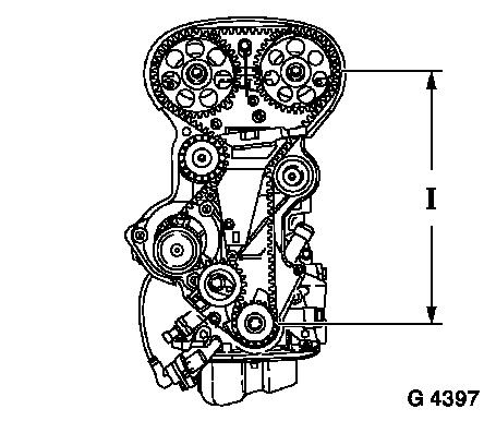
46. Install toothed belt
- Note: Note running direction and timing marks
- Position toothed belt
- Note: Tensioned side must be taut (I)
|
|
|
47. Tension toothed belt
- Tension toothed belt tension roller
- Turn adjusting eccentric in direction of arrow (anticlockwise)
until pointer of the toothed belt tension roller is located just
before left stop
- Fasten toothed belt tension roller bolt (1)
48. Remove KM-852
|
|
|
49. Timing, Check
- Turn crankshaft (720°)
- At crankshaft ribbed V-belt pulley bolt
- Note: In direction of engine rotation
- Set crankshaft to mark.
- Note: Marks on drive gear toothed belt and rear toothed belt
cover must align (III)
- Insert KM-852 (II)
- Note: Marks must be opposite one another and aligned with the
top edge of the cylinder head (I)
50. Remove KM-852
|
|
|
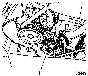
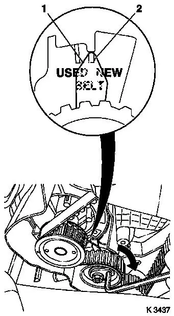
51. Toothed Belt Tension, Adjust
- Release toothed belt tension roller
- Turn adjustment eccentric in the direction of the arrow
(clockwise) until pointer (1) is aligned with the notch mark at the
toothed belt tension roller (2).
- Adjust used toothed belts to the marking USED
- Adjust new toothed belts to the marking NEW
- Tighten toothed belt tension roller bolt (20 Nm / 15 lbf.
ft.)
52. Toothed Belt Tension, Check
- Turn crankshaft (720°)
- Note: Pointers on the toothed belt tension roller and notch
mark must align
- Adjust used toothed belts to the marking USED
- Adjust new toothed belts to the marking NEW
|
|
53. Install lower part of toothed belt cover
- Clip to rear toothed belt cover
- Tighten bolts (4 Nm / 3 lbf. ft)
54. Install upper part of toothed belt cover
- Clip to rear toothed belt cover
- Tighten bolts (4 Nm / 3 lbf. ft)
55. Install right engine damping block
- Fasten engine bracket adapter
- Tighten bolts (60 Nm + 30° - 45°)
- Fasten engine damping block
- Tighten bolts (40 Nm / 29.5 lbf. ft.)
56. Raise vehicle.
57. Detach supports
- Engine timing side
- Transmission side
58. Remove KM-6169
59. Detach KM-6169-3
60. Install ribbed V-belt tensioner
- Tighten bolt (35 Nm / 26 lbf. ft.)
- Tension ribbed V-belt tensioner.
- Insert KM-6130
61. Attach crankshaft ribbed V-belt pulley
- Replace bolt
- Insert KM-911
- Tighten bolt (95 Nm / 70 lbf. ft. + 30° + 15°.)
- Remove KM-911
- Insert front closure plug
62. Install ribbed V-belt
- Note: Note running direction and installation position
- Release ribbed V-belt tensioner
- Remove KM-6130
63. Install ribbed V-belt cover
- Screw in bolts
- Install clip
64. Lower vehicle
65. Install right front wheel
66. Lower vehicle
67. Fasten right front wheel
- Tighten bolts (110 Nm / 81 lbf. ft.)
68. Install air cleaner housing
- Tighten bolt
- Install air intake hose.
- Attach engine vent hose
- Install air intake pipe
- Clip in tank vent valve
- Connect wiring harness plug.
69. Connect battery
70. Calibrate steering angle sensor
Note: Rotate the
steering wheel one time from its right-hand to its left-hand
stop.
71. Top up coolant
- Note: Top up and bleed cooling system – see operation
"Cooling System, Top Up and Bleed".
- Observe specified coolant quantity
72. Program volatile memories
73. Close bonnet
|
