Corsa C
|
Crankshaft Impulse Sensor, Petrol and Z19DT
Note: This operation does not apply to F4R engines. Objective: Checking Operation of the impulse sensor on the crankshaft. Measurement: Plot of voltage at the signal output for the impulse sensor on the crankshaft. Preparation: Switch off the engine and ignition. Connections:
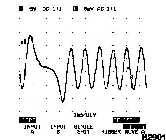
Procedure Tech 31:
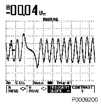
The change in the inductive voltage at the tooth gap of the crankshaft gear can sometimes be so small, that the signal cannot be triggered. In the event of this, the signal plot jumps on the display. However, longer observation of the display allows for the recognition of the impulse resulting from the tooth gap. The signal plot should be continuous and regular. If the amplitude of the signal plot varies greatly, in spite of the engine speed remaining constant, the crankshaft gear must be checked for soiling and concentricity. Procedure Tech 32:
Setup File:
The change in the inductive voltage at the tooth gap of the crankshaft gear can sometimes be so small, that the signal cannot be triggered. In the event of this, the signal plot jumps on the display. However, longer observation of the display allows for the recognition of the impulse resulting from the tooth gap. The signal plot should be continuous and regular. If the amplitude of the signal plot varies greatly, in spite of the engine speed remaining constant, the crankshaft gear must be checked for soiling and concentricity. |
||||||||||||||||||||||||||||||||||||||||||||||||||||||||