Corsa C
|
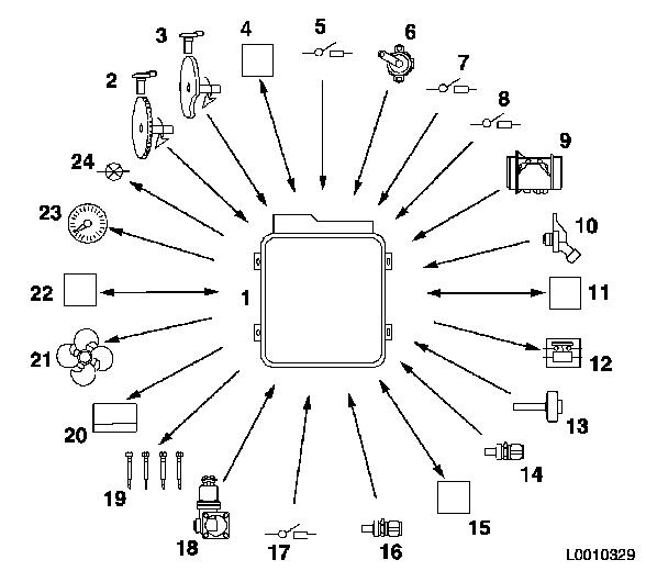
"MM 6JF" engine management system The Z 13 DT engine is fitted with the "MM 6JF" engine management system. Multijet injection has been used for the first time on an engine from the Ecotec engine series. The multijet injection system demands a lot from the engine management system. The engine management system has to continually correct the injection map, the number of injection processes and the quantity of diesel injected, depending on temperature, load and engine speed.
Key to diagram L0010329
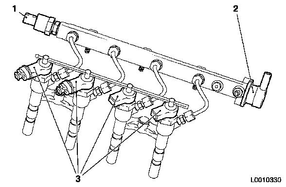
Rail pressure sensor The pressure sensor is bolted to the pressure accumulator on the timing side. The pressure sensor measures the current pressure in the pressure accumulator and sends a voltage signal to the engine control unit.
Pressure regulating valve The pressure regulating valve is bolted into the pressure accumulator on the transmission side. An electromagnet in the pressure regulating valve is actuated by the engine control unit; this opens a valve ball against spring force. Technical data:
Injectors Injectors (injector nozzles with electronically controlled valves) carry out injection processes at the right time and with exactly the right amount of fuel. The injectors are actuated by the engine control unit up to five times per expansion stroke.
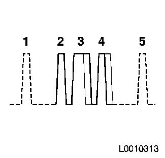
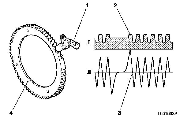
Crankshaft pulse generator When turning, the crankshaft pulse generator induces a voltage in response to the generator disc teeth. The sine curve indicates the AC voltage which arises in the process. Its frequency (oscillation frequency) is dependent on the rotational speed of the pulse wheel. The pulse generator disc is attached to the rear of the flywheel.
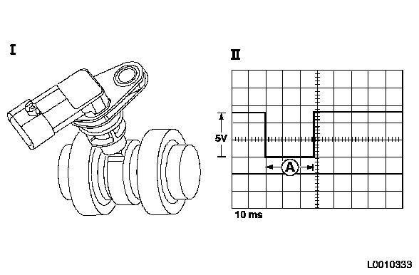
Camshaft sensor The camshaft sensor is installed in the camshaft housing and scans the position of the exhaust camshaft. Using Hall-effect pickups on the camshaft, the position of the camshaft is recorded and the signal sent to the engine control unit.
Air mass meter The air mass meter sits between the air filter and the air intake pipe, has two tasks and sends signals to the engine control unit.
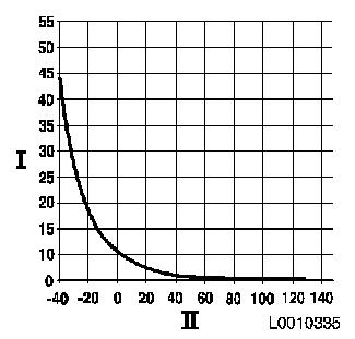
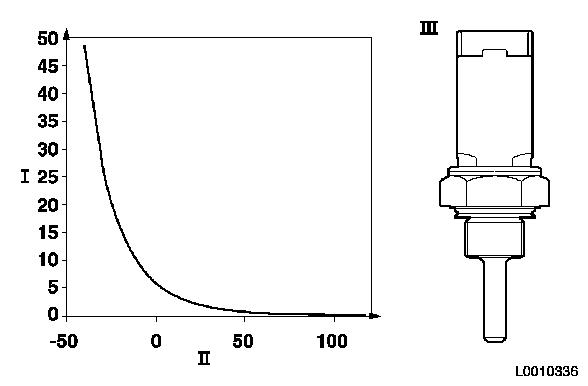
Coolant temperature sensor The coolant temperature sensor is installed in the thermostat housing. The resistance of this sensor decreases as temperature increases.
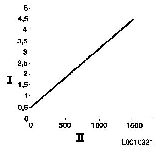
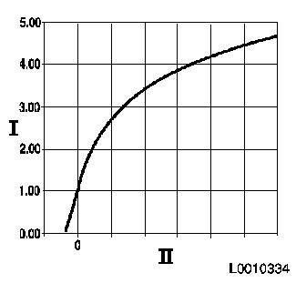
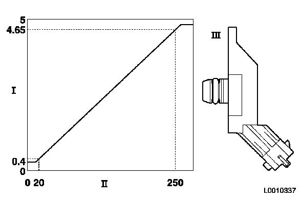
Charge pressure sensor The charge pressure sensor is installed in the inlet manifold. The output signal to the engine control unit is 0 to 5 volts.
|
||||||||||||||||||||||||||||||||||||||||||||||||||||||||||||||||||||||||||||||||||||||||||||||||||||||||||||||||||||||||||||||||||||||||||||||||||||||||||||||||||||||||||||||||||||||||||||||